Kōkeʻe Park Geophysical Observatory Site News
The Navy and NASA are jointly preparing an Environmental Impact Statement (EIS) for real estate agreements at PMRF and KPGO
June 20, 2025
The U.S. Department of the Navy (Navy) and the National Aeronautics and Space Administration (NASA) have jointly prepared a Draft Environmental Impact Statement (EIS) to evaluate the potential environmental impacts of proposed real estate agreements with the State of Hawai‘i for the Pacific Missile Range Facility (PMRF) and the Kōke‘e Park Geophysical Observatory (KPGO). Public involvement is an integral part of the environmental planning process. The public has an important role in providing input during this process to help the Navy and NASA make more informed decisions about the proposed real estate action including on the environmental impacts of the alternatives, environmental or cultural concerns, information the public would like the Navy and NASA to know, and any other information the public would like to see addressed in the Final EIS.
Between July 15 and July 17, the Navy and NASA will host public meetings at three locations on Kaua‘i. Each meeting will be held from 5 - 8 PM HST and include a live online broadcast and public comment opportunity. Please visit the PRMF & KPGO EIS website to learn more about the real estate action, the environmental planning process, the public meetings or to register for the live online broadcast, or how to submit comments: https://pmrf-kpgo-eis.com/.
The Navy and NASA are jointly preparing an Environmental Impact Statement (EIS) for real estate agreements at PMRF and KPGO
May 08, 2024
The U.S. Navy and the National Aeronautics and Space Administration (NASA) are jointly preparing an Environmental Impact Statement (EIS) to evaluate the potential environmental impacts of proposed real estate agreements with the State of Hawai‘i for the Pacific Missile Range Facility (PMRF) and the Kōkeʻe Park Geophysical Observatory (KPGO). Public involvement is an integral part of the environmental planning process. The public has an important role in providing input during this process to help the Navy and NASA make more informed decisions about the proposed real estate action including potential alternatives, environmental or cultural concerns, information the public would like the Navy and NASA to know, and any other information the public would like to see addressed in the EIS.
Please visit the PRMF & KPGO EIS website to learn more about the real estate action, the environmental planning process, or how to submit comments: https://pmrf-kpgo-eis.com/.
The Navy and NASA are jointly preparing an Environmental Impact Statement (EIS) for state lands at PMRF and KPGO
December 15, 2023
The Navy and NASA are jointly preparing an Environmental Impact Statement (EIS) to evaluate the potential impacts of real estate agreements with the State of Hawai'i, Department of Land and Natural Resources (DLNR) for state lands at PMRF and KPGO. The Navy and NASA encourage the public to participate in this environmental review process. The Navy and NASA will be initiating a public scoping period and holding public meetings in early 2024. The public can participate during the public scoping period by providing input on the proposed real estate action and issues to be considered in development of the EIS.
View fact sheet
The National Geodetic Survey posts the results of their May 2023 local tie survey at the NASA Kōkeʻe Park Geophysical Observatory (KPGO)
October 26, 2023
The National Geodetic Survey posted the results of their May 2023 local tie survey at the NASA Kōkeʻe Park Geophysical Observatory (KPGO). The survey establishes high-precision local tie vectors between the geodetic stations and their associated reference marks. Data collection consisted of terrestrial observations with an absolute laser tracker system, a total station, and survey-grade GNSS instrumentation. The local relationships were aligned to the International Terrestrial Reference Frame at the epoch date of the survey, ITRF2020 (2023/05/13). The survey results, report, and SINEX file are available at the NGS website: https://www.ngs.noaa.gov/corbin/iss/index.shtml.
KPGO Operations Welcomes New Technician
September 18, 2023
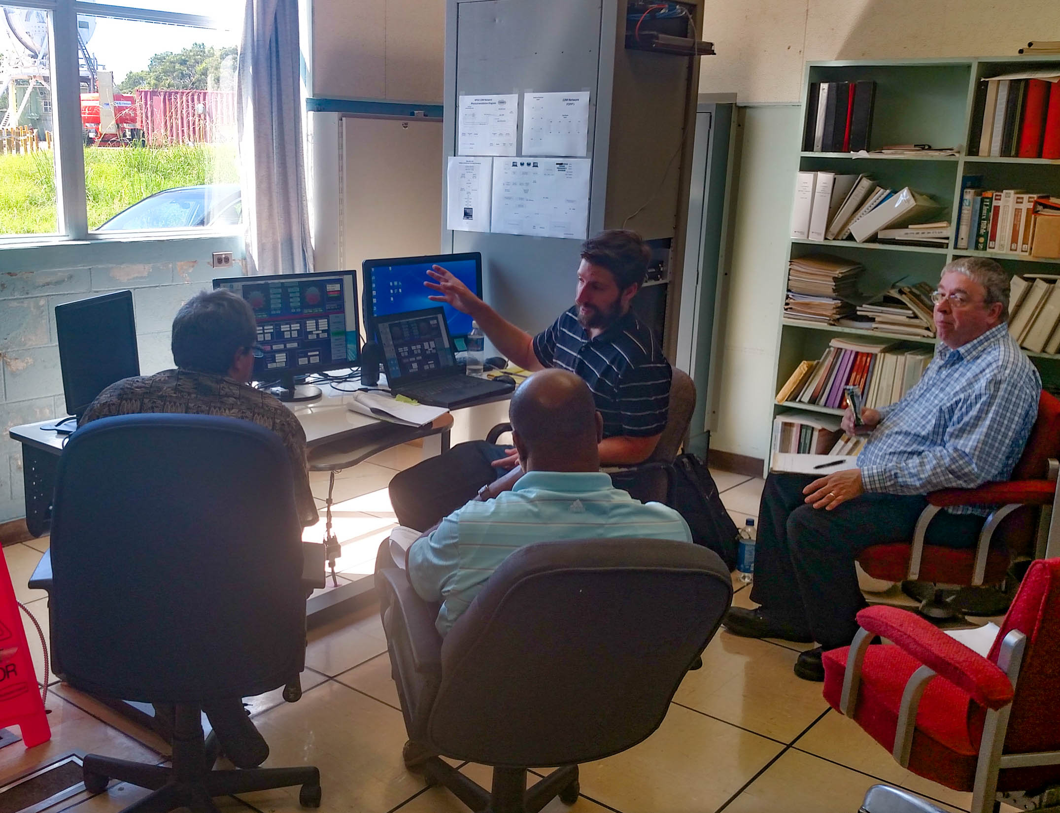
New employee Glenn Victa has joined the KPGO operations team.
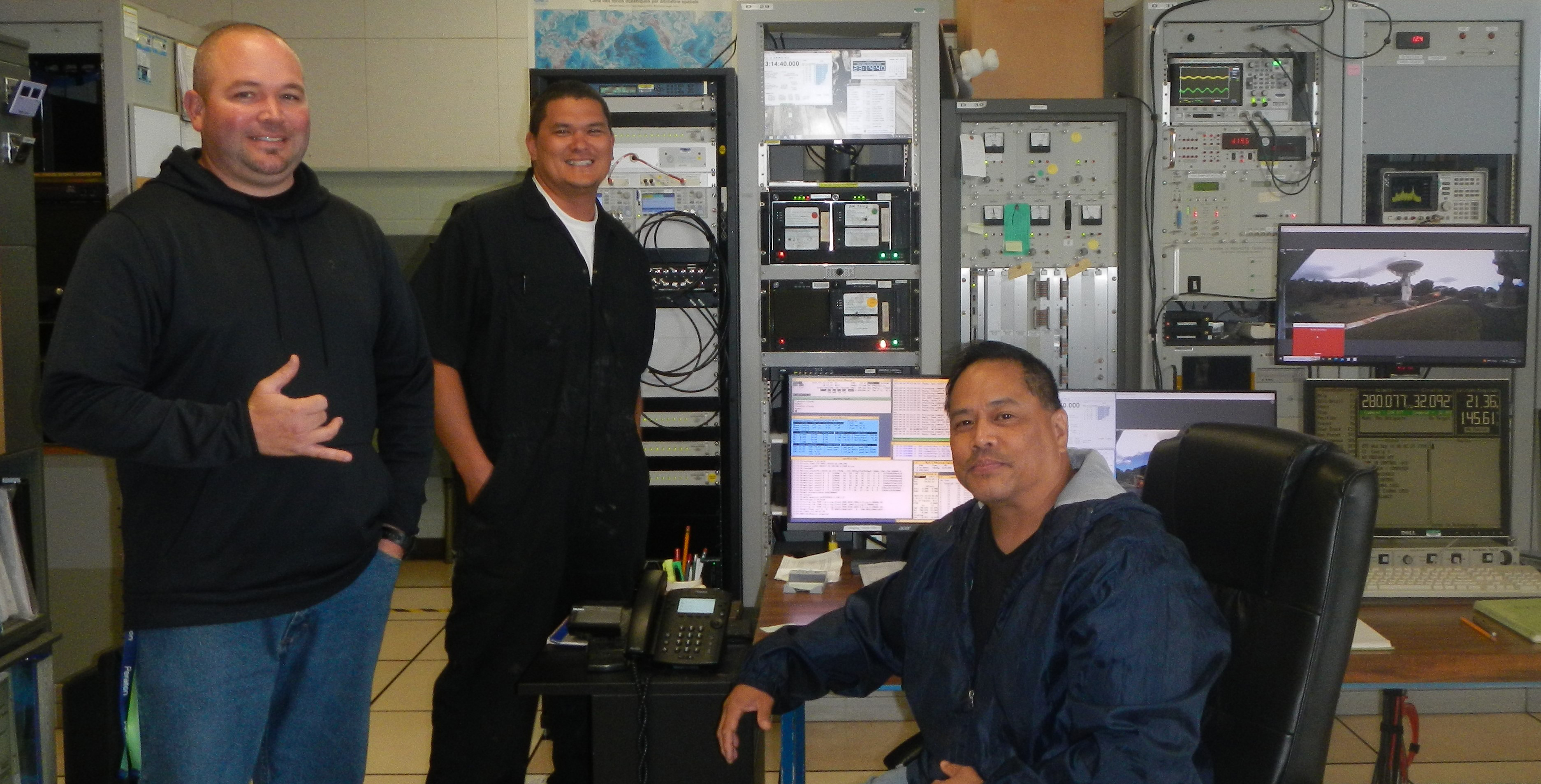
From left to right: Chris Coughlin (KPGO Station Manager), Kiah Imai (KPGO Lead Engineer) and new engineering technician Glenn Victa
New Maser Arrives at KPGO
June 30, 2023
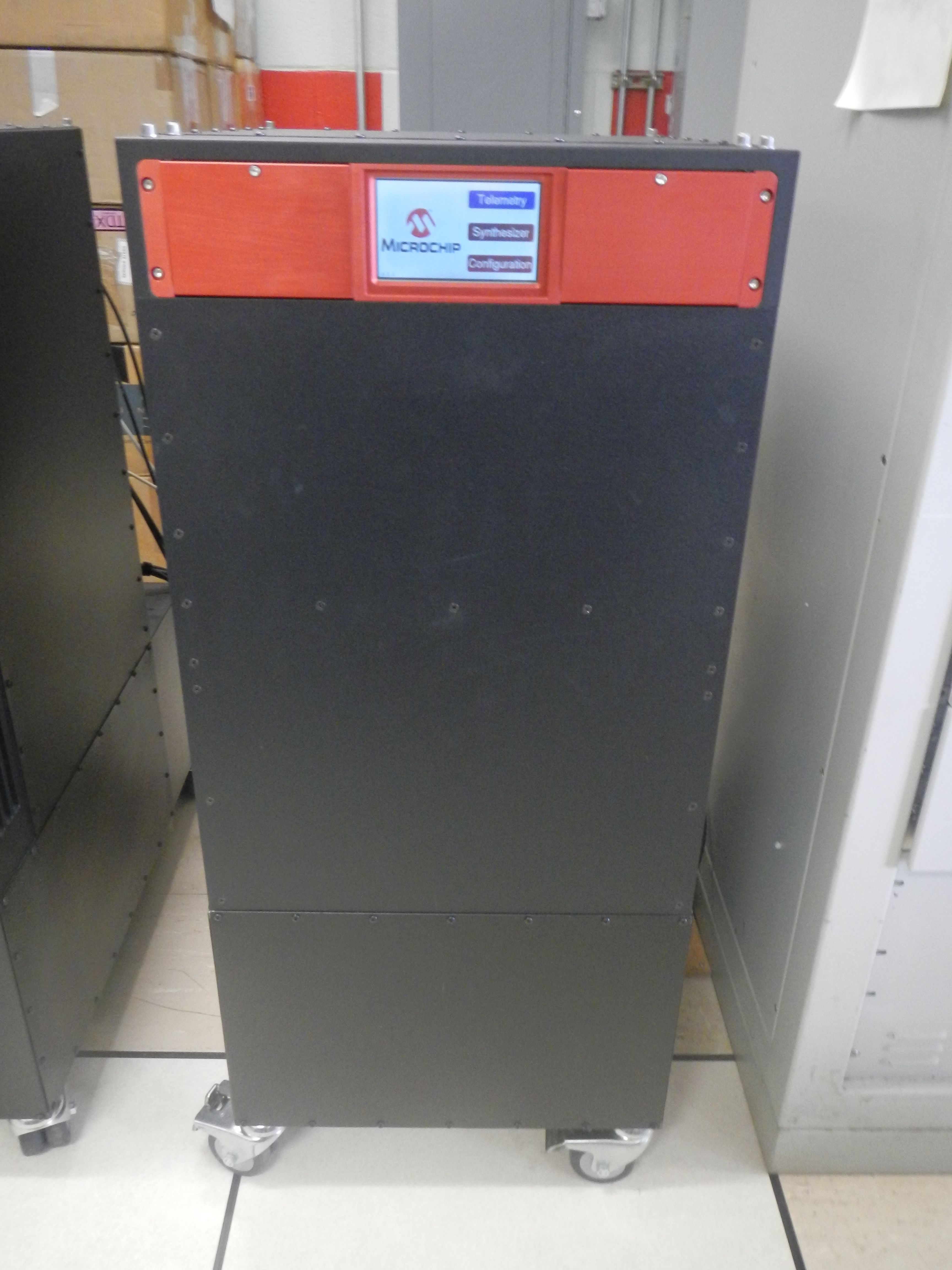
A new MHM-2020 model Sigma-Tau Maser (SN:371) manufactured by Microchip, Inc. was delivered to KPGO. Station operations is monitoring the hydrogen maser stabilization process which typically requires 60 – 90 days to complete. A maser is critical to operations because it maintains stable, accurate time measurements across all connected instrumentation.
New Maser Arrives at KPGO
NASA Celebrates 60 Years with Kōkeʻe State Park on Kauai
June 1, 2023
As a tracking station for the Mercury and Gemini programs in the early 1960s, the state of Hawaii and NASA have shared historic advancements in space science.
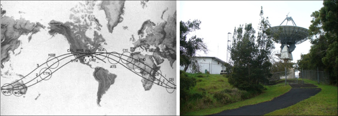
The station at Kokee Park Geophysical Observatory (KPGO) served NASA from 1961 – 1965 as a tracking station (HAW) during Mercury and Gemini space flight programs. In the mid-1980s, the station transitioned to other science missions committed to NASA Space Geodesy Project using radio telescope instrumentation mounted on antenna systems. NASA provides access to the site to the Hawaii Department of Land and Natural Resources and the US Navy and welcomes native and local groups as part of NASA's Space Geodesy educational outreach program.
NGS Survey Completed
May 18, 2023
A team from the National Geodetic Survey (NGS) was on-site to provide a re-survey of the KPGO station. The survey was performed to validate a new geodetic measurement technique that provides increased precision.
Operations Team Supports DORIS Instrumentation Upgrades
April 18, 2023
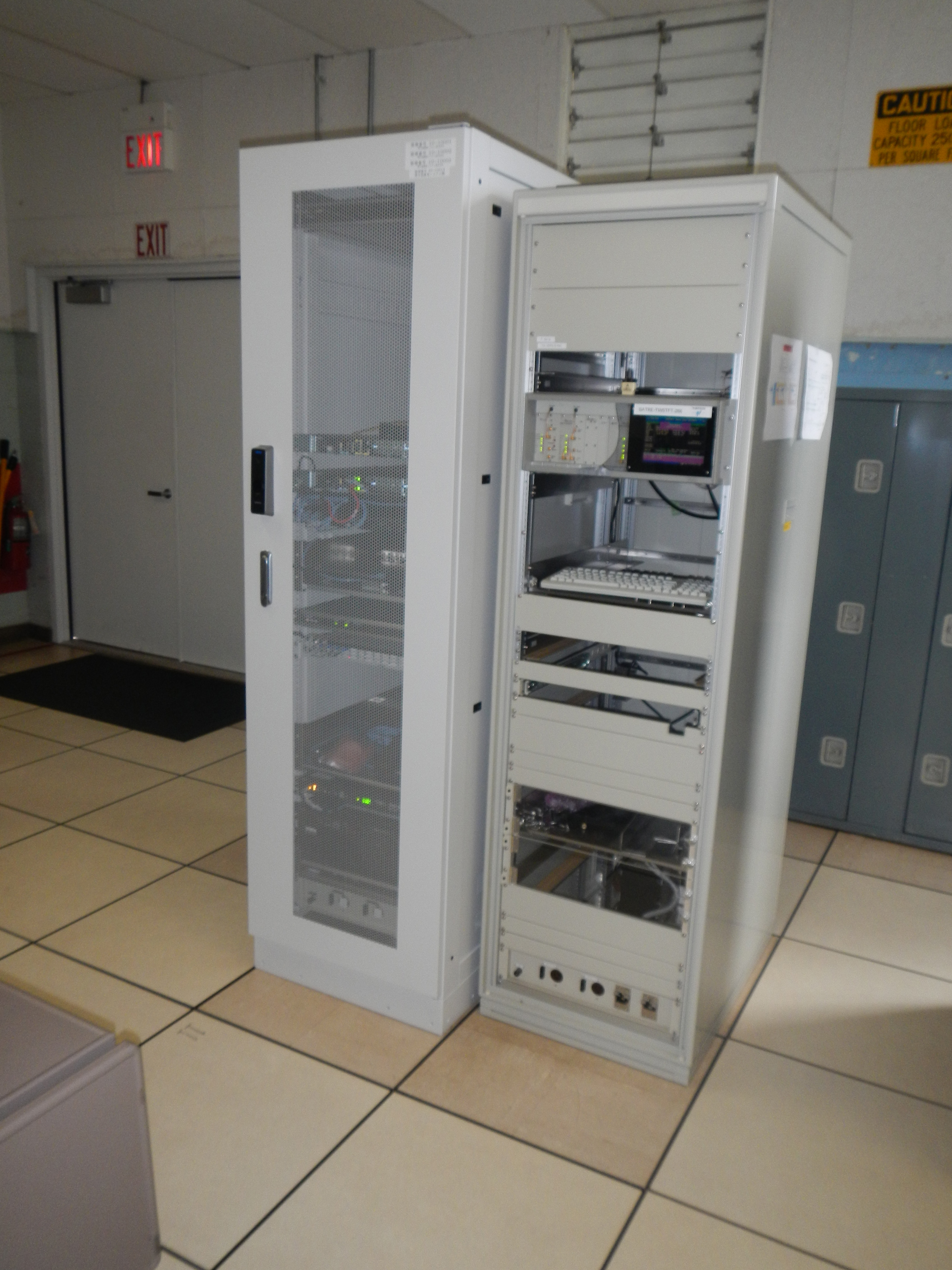
KPGO operations supported the French National Space Agency for Space Studies (CNES) during installation of new equipment to support 2024 mission objectives proposed for Doppler Orbitography by Radiopositioning Integrated on Satellite (DORIS).
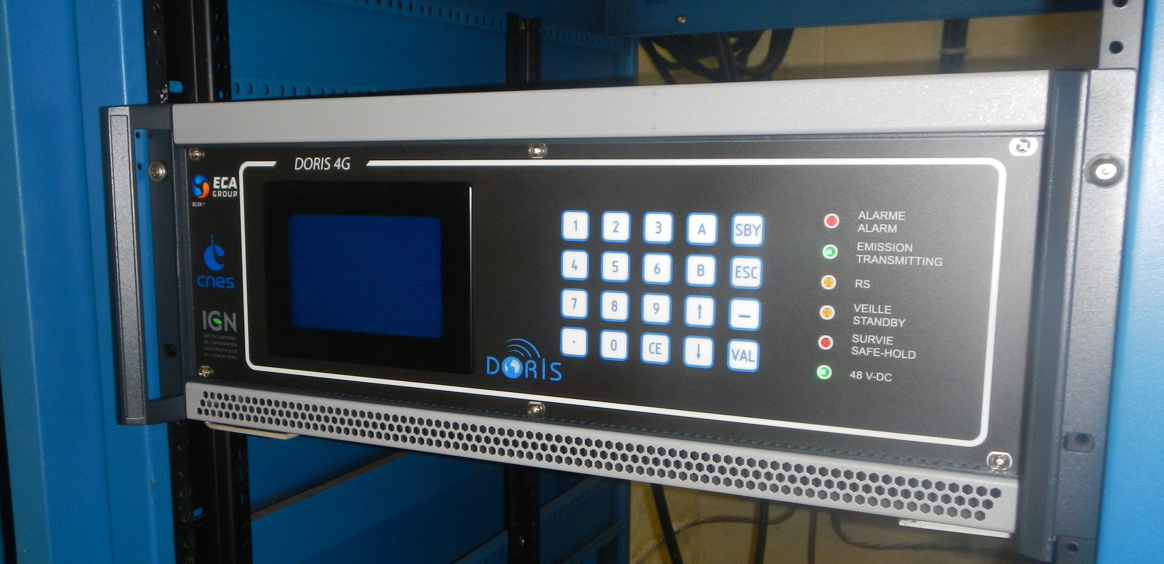
DORIS receiver equipment located in the main operations center.
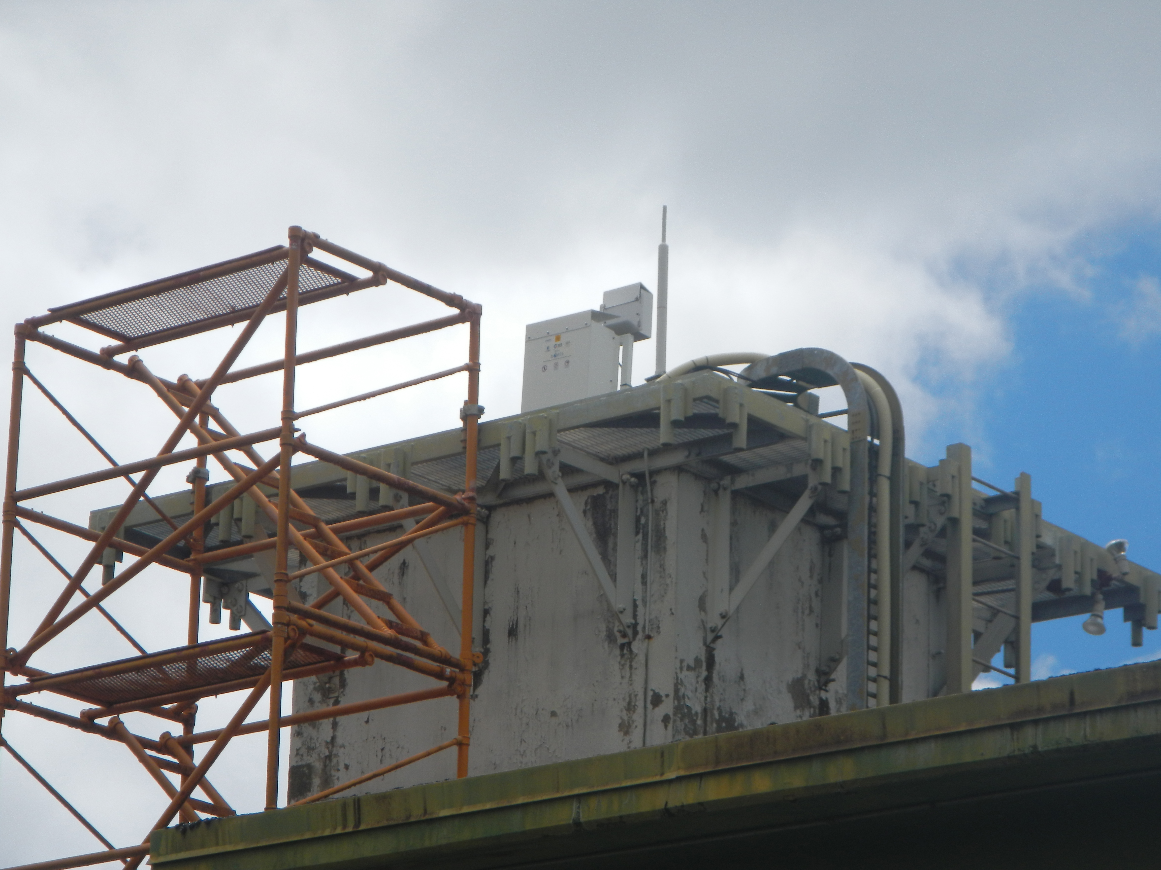
DORIS antenna instrumentation located on roof of the operations building.
Operations Team Supports QZSS Equipment Installation
March 9, 2023
KPGO operations personnel supported the installation of a new Quasi-Zenith Satellite System (QZSS) station, including a Met4a weather station, replacing the original QZSS station at the site.
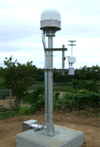
A new GNSS antenna and weather instrumentation were installed at KPGO in March 2023 to support Quasi-Zenith Satellite System (QZSS).
Equipment installation in the operations center to support future QZSS support.
20-Meter Antenna Completes 30 Years of Service to IVS
December 31, 2022
The 20-Meter antenna celebrated 30 years to the NASA Space Geodesy Project campaign. The system receiver is of NRAO design configured with dual polarization feed using cooled 15 K HEMT amplifiers. The antenna is of the same design and manufactured similarly as those used at Green Bank, WV. and Ny-Ålesund, Svalbard. A Mark 5B+ recorder is currently used for all data recording tasks.
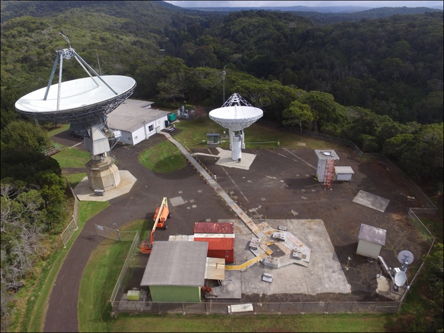
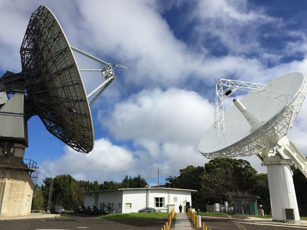
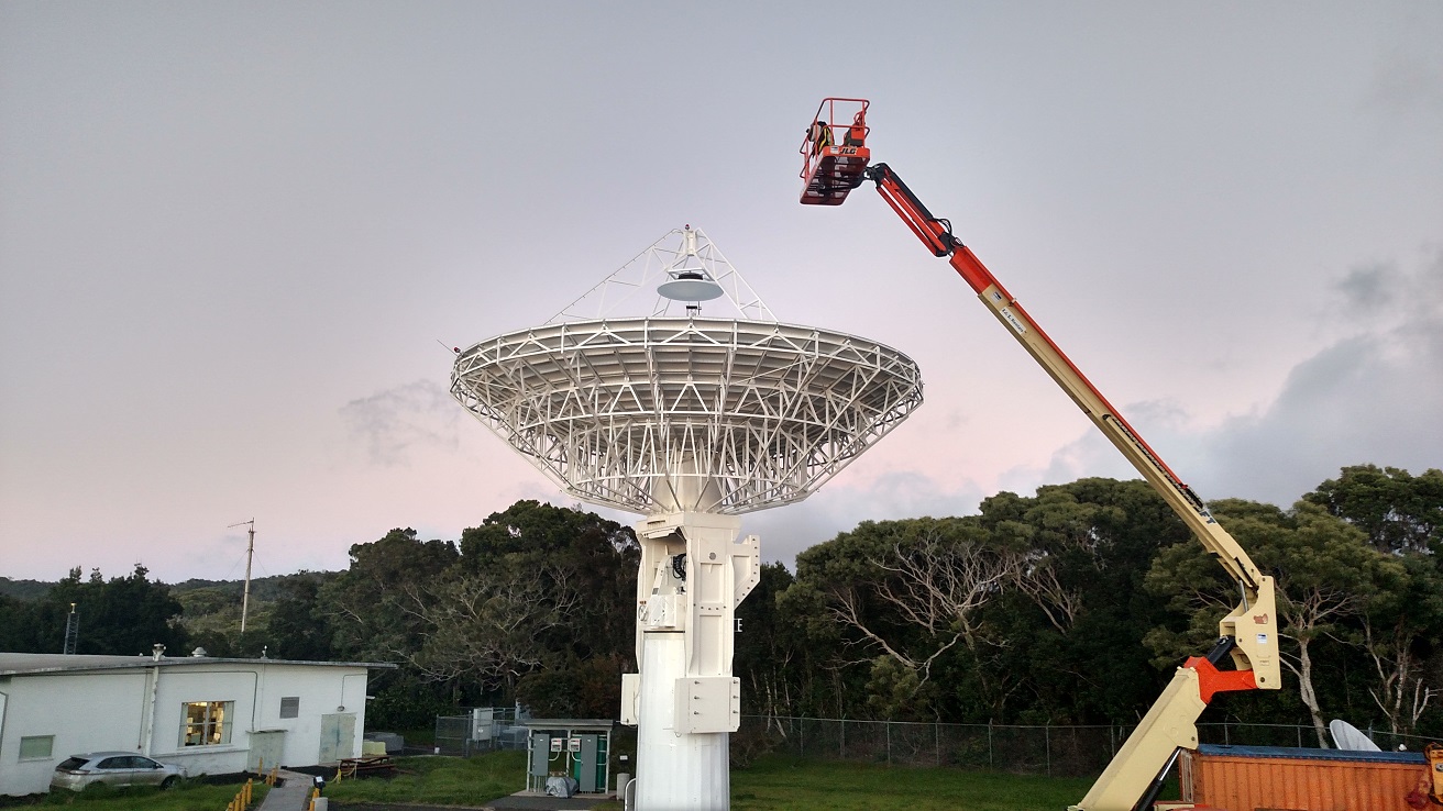
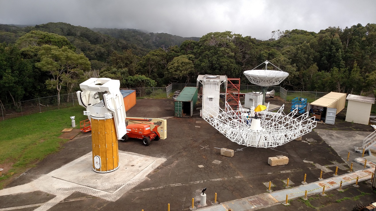
An aerial view of the Kokee Park Geophysical Observatory (KPGO) located in Kokee State Park on Kauai Island. The new 12-meter antenna system is shown at center. The older, larger 20-Meter antenna (left) has been supporting NASA earth and climate scientific research for over 30 years but will eventually be decommissioned and removed once the next-generation VLBI Global Observing System is fully operational and replaces the legacy VLBI network.
Successful VGOS Observation Campaign (2021)
December 31, 2021
The 12-Meter (k2) and 20-Meter (kk) antenna systems completed successful 2021 SGP mission campaigns. The 12m antenna logged 98% of weekly IVS scheduled observations. The legacy 20m system scored nearly 100% of all 42,046 scheduled scans.
Kelly Kim and Ben Domingo Retirement
October 15, 2021
Previous Station Manager and long-time KPGO technician Kelly Kim retired after 45 years of service to NASA in Kokee Park. In addition, long time KPGO technician Ben Domingo announced his retirement after 22 years of service to NASA in Kokee Park. NASA extends best wishes and congratulates both individuals on their dedication and commitment to the Space Geodesy Project.
Kelly Kim
Ben Domingo
KPGO ISO/AS9100 Audit Completed
July, 2021
Station management and operations achieved certification for compliance with ISO/AS9100 standards. Certification represents execution of a Quality Management System that consistently provided products that meet NASA regulatory requirements.
Operations Staff Return to Normal Schedule During COVID
April 15, 2021
KPGO staffing plan and shift rotation returned to normal schedule operations implementing COVID safety protocols.
Successful VGOS Observation Campaign (2020)
December 31, 2020
The 12-Meter (k2) and 20-Meter (kk) antenna systems completed successful 2020 mission campaigns despite lingering COVID-19 restrictions. Station personnel followed COVID-19 protective regulations and still managed to log 95-99% of weekly IVS scheduled observations. All major upgrades, however, are on temporary hold until COVID restrictions are relaxed per NASA safety recommendations.
Network Upgrades Completed
October 2019
KPGO completed a major site network upgrade to a new NASA-compliant configuration, hardware, and protocols. Network upgrades not only improved overall site network performance, but also data e-transfer speeds. This new data rate reduces time required to transmit all VLBI data and reduces the dependency on module shipments.
Successful VGOS Observation Campaign (2017)
December 31, 2017
The 12-Meter (k2) and 20-Meter (kk) antenna systems completed successful 2017 campaigns. Station operations participated in many VLBI experiments including IVS R4 and R1 experiments. The station also participated in the RDV, CRF, APSG, RD, and OHIG experiments. KPGO averaged two 24-hour experiments weekly along with weekday Intensive experiments. There were no major e-transfer link outages reported in 2017, providing quicker delivery of INT1 data to the WACO Correlator and better latency results.
12-Meter ISI Antenna (k2) Joins the IVS Observation Schedule
April 2017
Following commissioning tests and a successful ORR, the VGOS 12-Meter radio telescope officially joined the VGOS Observing Schedule. Along with the 20-Meter system, KPGO operations now support scheduled observations on two NASA-managed antenna systems.
New 12-Meter Antenna Passes Operational Readiness Review
March 2017
KPGO VGOS 12-Meter radio telescope passed the operational readiness review (ORR) following installation activities starting in May 2015. Site operations are planning to join the VGOS Observation Schedule in April 2017.
New antenna preparing for graduation and entering the VLBI workforce
May 13, 2016
It is graduation season, and the new VGOS 12-m antenna at KPGO is nearly ready to transition to operations!
The freshman antenna arrived in September 2015, understandably anxious about that first semester. With a solid foundation and pedestal to stand on, she spread an intricate web of beams and struts, and topped her top with a sea of reflecting panels. Under the long-shadow of the 20-meter, the next generation antenna continued to blossom and grow.
The VGOS signal chain installed in January 2016 opened her eyes to new sights and possibilities. She quickly learned to collaborate with her older siblings across the ocean at Westford and GGAO. The three antennas can now routinely observe in broadband continuously for 24 hours!
With the senior 20-meter antenna about to have open heart surgery on its main bearing, it was important to pass the geodetic knowledge to the new generation as quickly as possible. A series of observing sessions provided the link at the millimeter-level between the two KPGO antennas. The KPGO handoff was successful and the 20-meter antenna is now getting much needed repairs.
The new antenna is now ready to reach out to the rest of the world and has started learning new languages. A series of compatibility test were performed with several European stations that are also anxious to join the VGOS network.
With just a few more tweaks and tests, our young antenna is ready to graduate and join the greater VLBI workforce. We expect to hold an Operational Readiness Review within the next two months. With the intensive commissioning activities coming to an end, this will be the final entry to this blog. Please continue to visit the SGP website for news and updates. Its been fun sharing our progress with you.
-- Larry Hilliard, Pedro Elosegui, Stephen Merkowitz, and the rest of the SGP team.
Historic handoff at KPGO from a metaphorical 12-m antenna standing guard and seeking out quasars sky-wide while legacy 20-m antenna gets needed repairs to her azimuth bearing, to play a reduced role during her extended life, and making way for a new generation.
Connecting the old with the new
February 29, 2016
The legacy 20m VLBI antenna at KPGO will undergo a major refurbishment later this year. The procedure involves lifting the main reflector off its bearing. The time lapsed video below shows what was involved in lifting the much smaller 12 meter reflector back in October 2015. In the next few months, the 20 meter reflector will be lifted as well using mechanisms to enable a life extending bearing replacement.
The bearing replacement will change the antenna "reference" location that has been established by VLBI over the past decade. It is vital that we do not lose continuity at the site, so in addition to the precise ground survey that was performed earlier this year, we are making a series of "short-baseline" VLBI observations using both the old and the new antennas at KPGO to establish the tie between these two antennas. These observations will also be an excellent test of the "mixed mode" technique that makes the broadband and the legacy S/X networks compatible. The continuity of geodetic legacy and broadband network locations at KPGO can then be re-established after the bearing replacement with verifiable before and after tests.

A geodetic tie can be made between the old and new antennas at KPGO by making a series of short-baseline VLBI observations using the mixed mode technique. Seen here are the two antennas simultaneously observing source 0235+164 on February 12.
Connecting to the Past – Present Network, Transitioning to the Future
February 19, 2016
The first fringes recently obtained with the 12-meter antenna marked the dawn of the VGOS broadband era. But there is also an important linkage to the existing “legacy S/X” VLBI network that is right next door and connected around the world. Indeed, the 20-meter antenna at KPGO, which is currently configured to observe with the legacy S-band and X-band receivers that are operational at VLBI geodetic sites worldwide, can also form baselines with the new broadband systems under a “mixed-mode” configuration that makes the broadband and the legacy S/X networks compatible.
On February 12, the KPGO operational team run a mixed-mode fringe test with the KPGO 12-meter and 20-meter antennas configured in broadband and legacy S/X modes, respectively. The mixed mode produced the first fringes thus establishing a short baseline that ties over 20 years of operation with the legacy VLBI network to the broadband VGOS network of the future.
An intra-KPGO short-baseline tie can be realized by configuring (left) the 20-meter antenna as a legacy S/X VLBI system and (right) the 12-meter antenna as a broadband VGOS system using common observing frequencies and a mixed-mode correlation method.
First Light!
February 17, 2016
Having completed the installation of the signal chain, the team turned the antenna toward the sky on February 1 and observed peaks on Taurus A, Orion and 3C84! On February 5, we ran two coordinated sessions observing several strong radio sources using the new KPGO antenna and the antennas at Westford in Massachusetts and at the Goddard Geophysical and Astronomical Observatory (GGAO) in Maryland. Each session used a different pointing model for KPGO to maximize the chance of success. Once completed, the data from a selected scan (1749+096) from all three sites were transferred over the Internet to the correlator at MIT Haystack for cross-correlation and fringe search. Fringes for the Westford-GGAO baseline were found quickly, as one would expect, given the practice and experience gained with this VGOS-prototype baseline over the last year. Despite the long baselines to KPGO, the search to KPGO was not overly taxing either because the KPGO site position and maser behavior of KPGO (both derived from the KPGO 20m model) that are required as a priori model in the correlator were accurate enough to help narrow the fringe search to a relatively small window, hence expediting the process.
This represents a major milestone for the Space Geodesy Project and is the world's first 3-way broadband VLBI measurement. It was also the first long baseline broadband VLBI measurement, demonstrating the viability of the next-generation antenna for improving determination the Terrestrial Reference Frame and Earth Orientation Parameters.
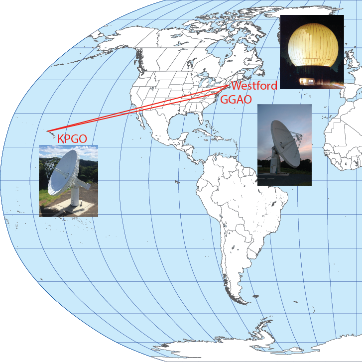
The transoceanic baselines demonstrate the viability of broadband VLBI that will contribute to the accuracy improvement of the Terrestrial Reference Frame and Earth Orientation Parameters, the building blocks of all space missions and geophysical applications.
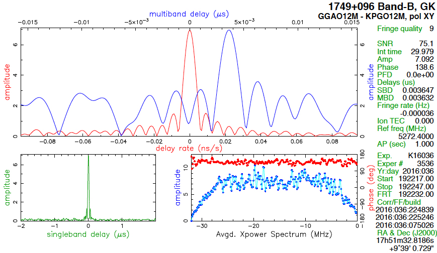
Broadband VLBI "fringes" were obtained on the extragalactic radio source quasar 1749+096. Shown here are the fringes for the long transoceanic baseline between Hawaii and Maryland.
Installation and Integration of Signal Chain Frontend Components at KPGO
February 01, 2016
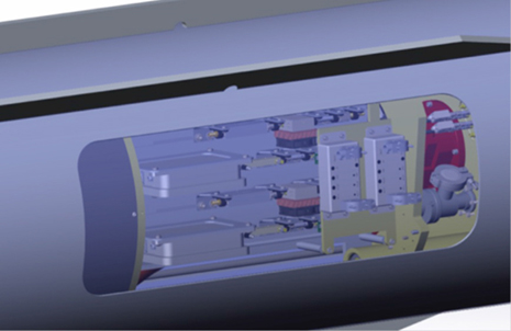
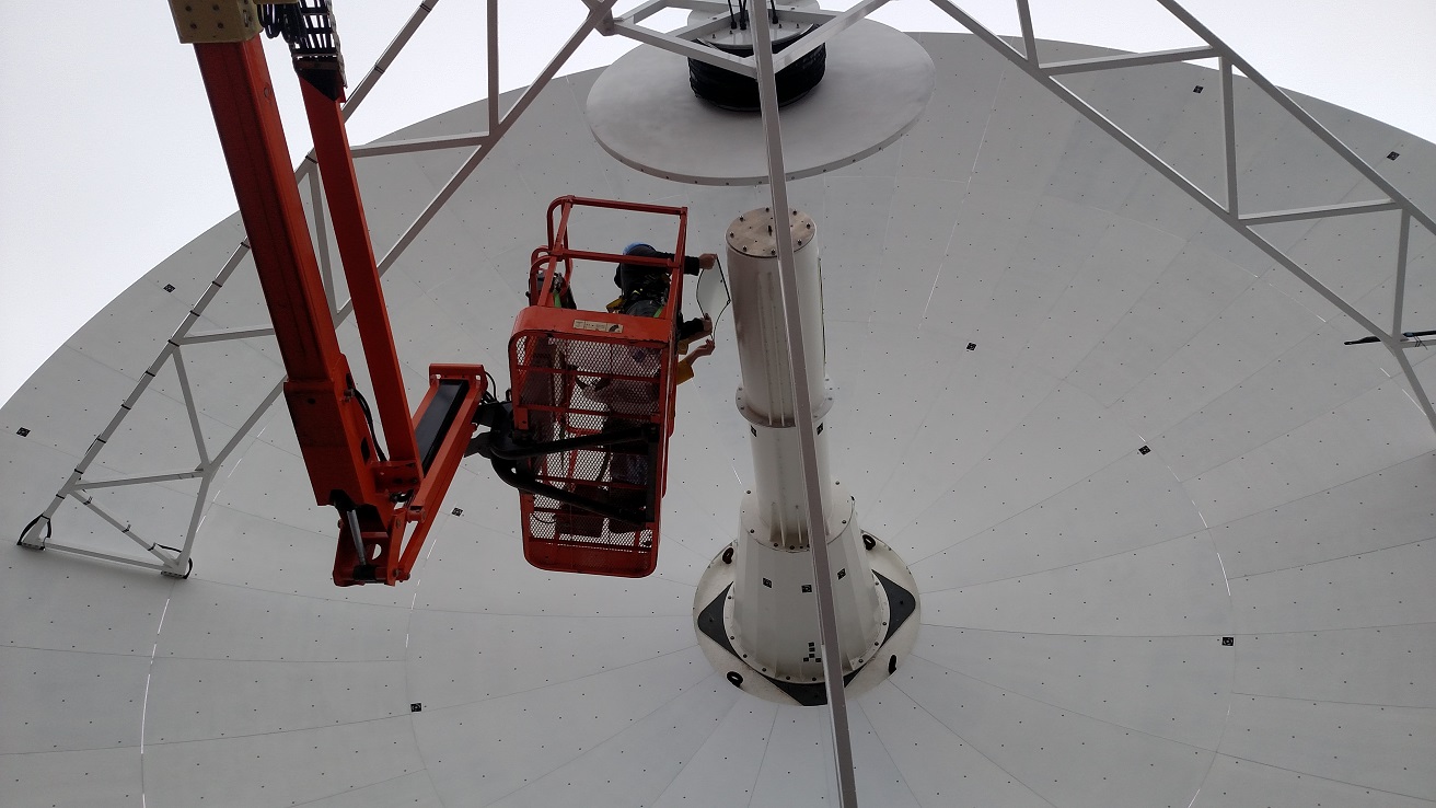
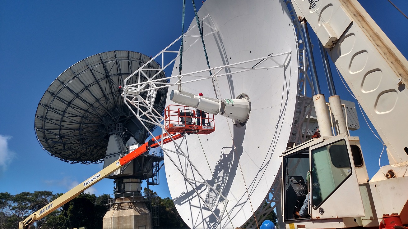
The KPGO Signal Chain integration team arrived at KPGO on January 18 and immediately inspected the frontend hardware and tools, as well as the personal protection equipment necessary for operating safely in the antenna frontend environment. The team then proceeded to installation, integration, and verification of the frontend subsystem. The visuals below illustrate some of the subsystems of the assembled frontend such as the positioner, payload, hub electronics, vacuum pump, uninterrupted power supply, compressor, post-dewar electronics sled, and the monitor and control infrastructure.

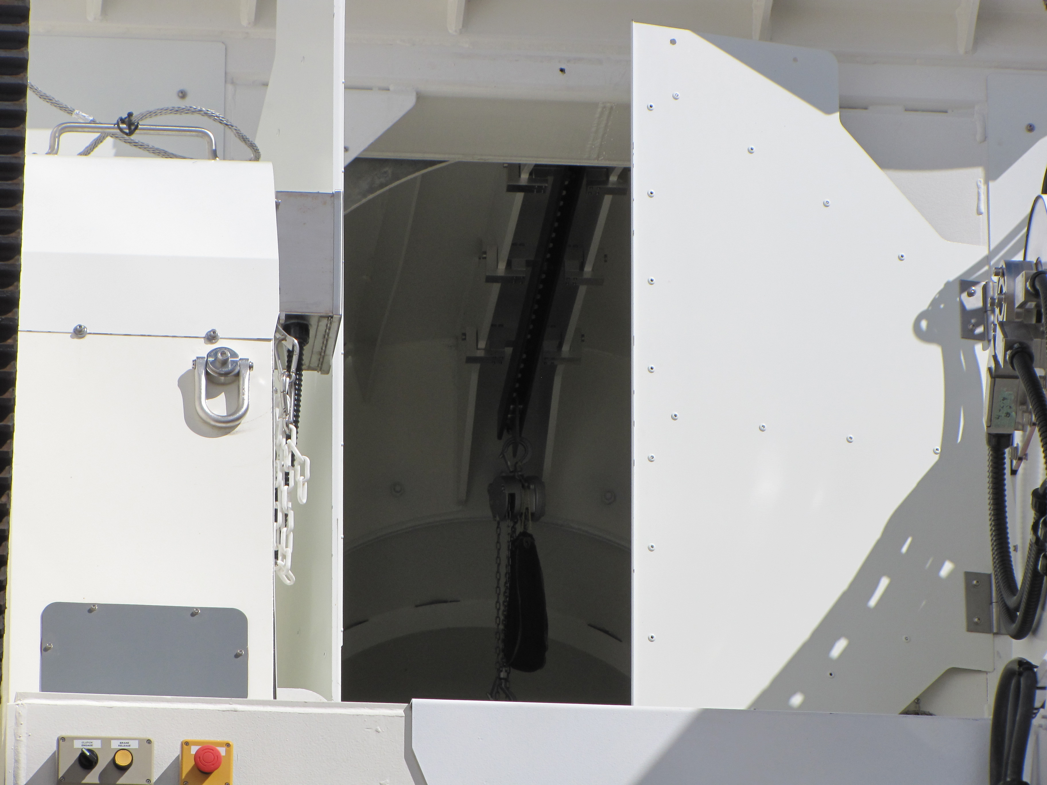
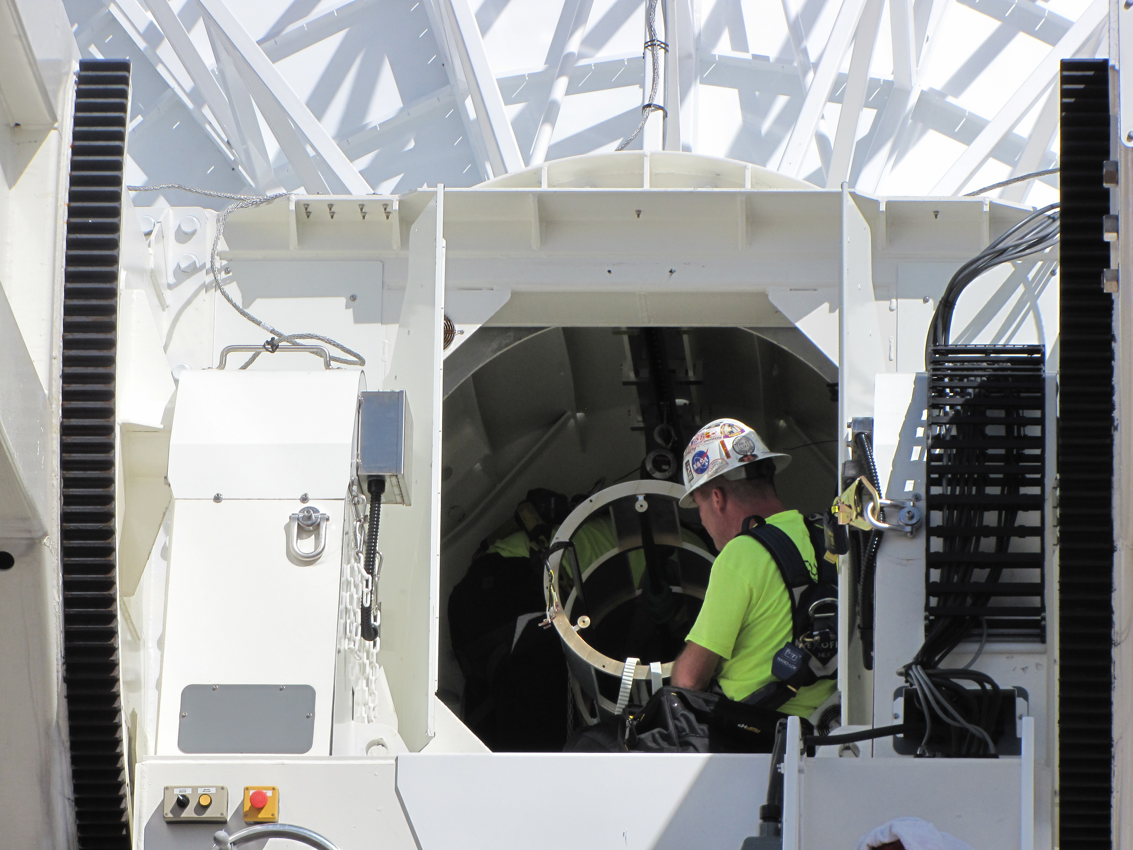
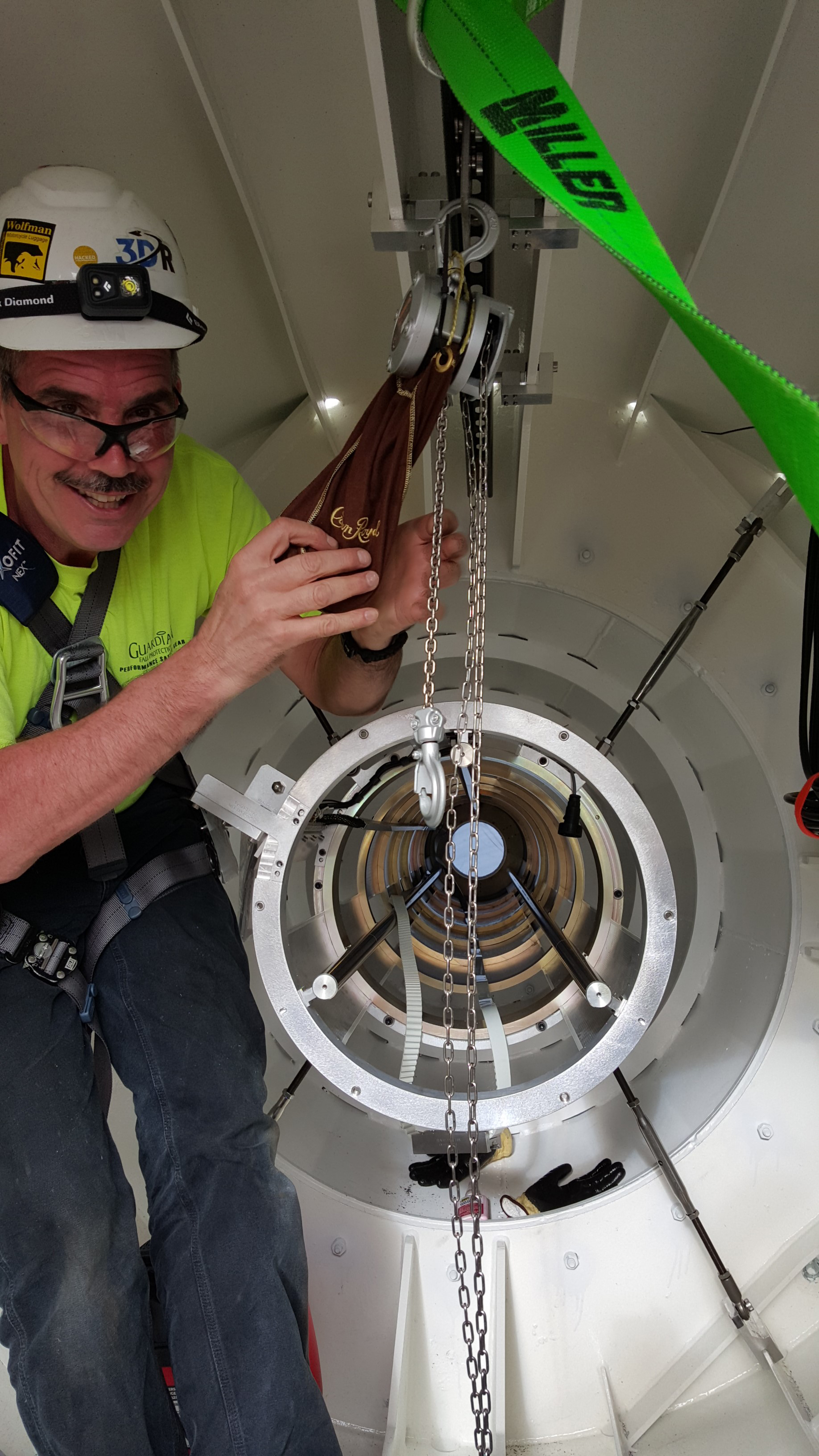
The frontend installation began with the attachment of the signal chain/feed cone interface ring, then an installation of the hoist trolley to enable the insertion of the frontend positioner (FEP) middle subassembly, until four tie rods could secure the hub end, and the signal chain/feed cone interface ring at the other end.
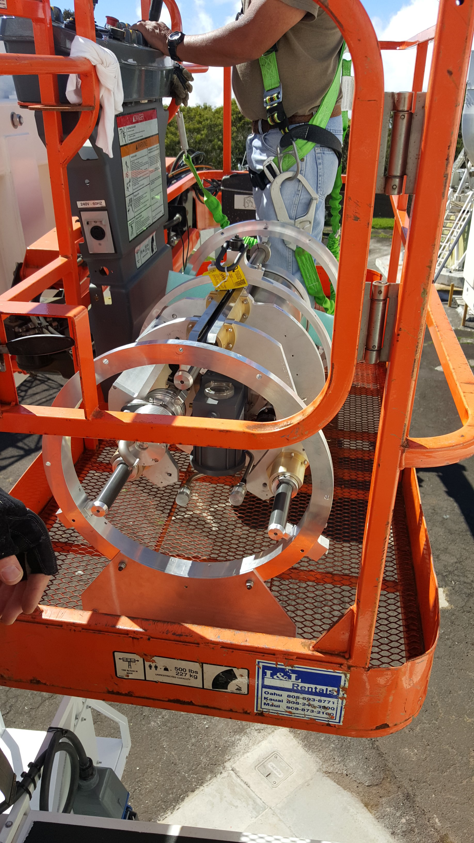
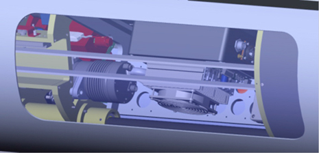
The frontend payload was put on the rail extensions using the caddy designed to mate with the frontend positioner system.

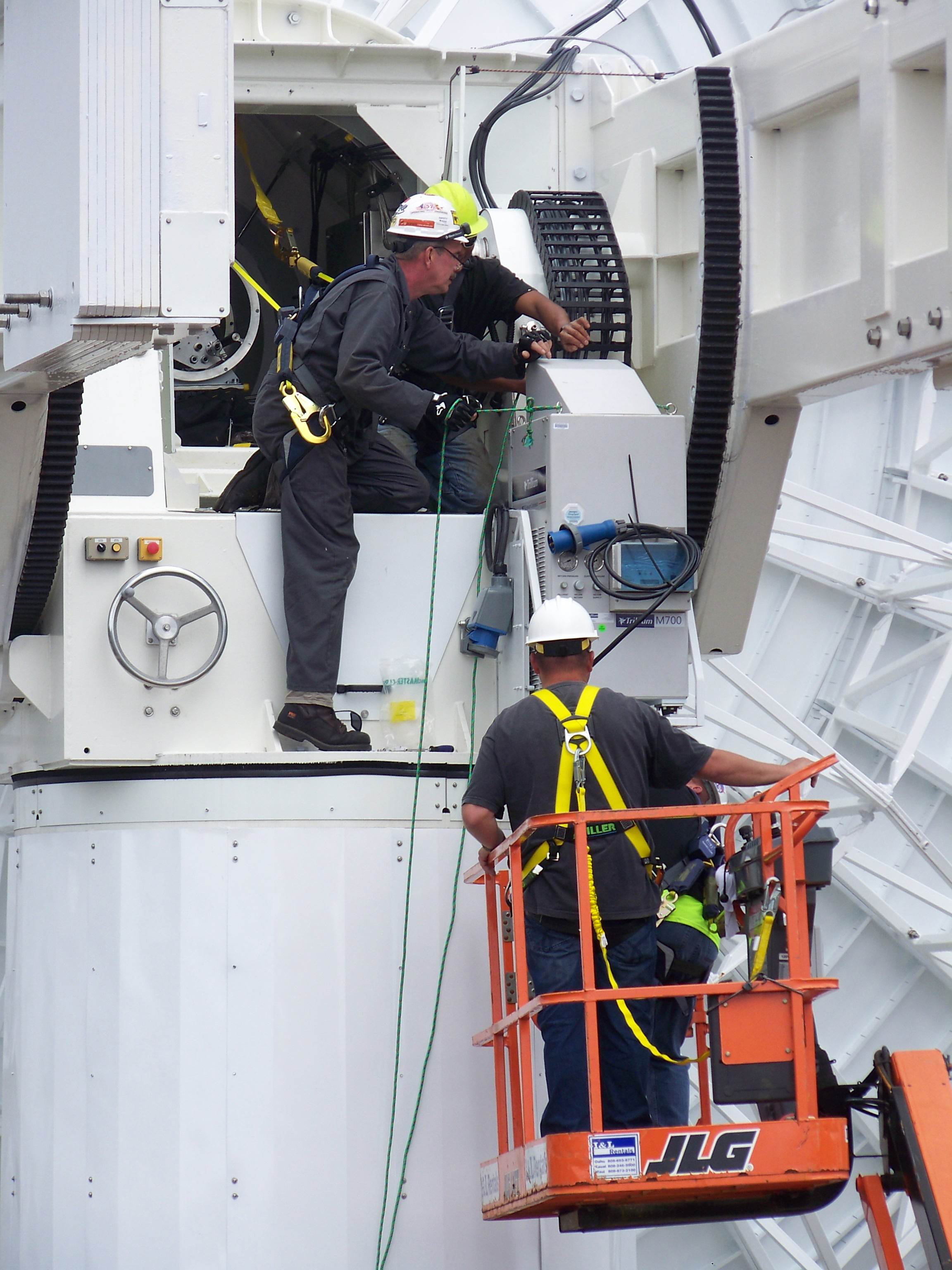
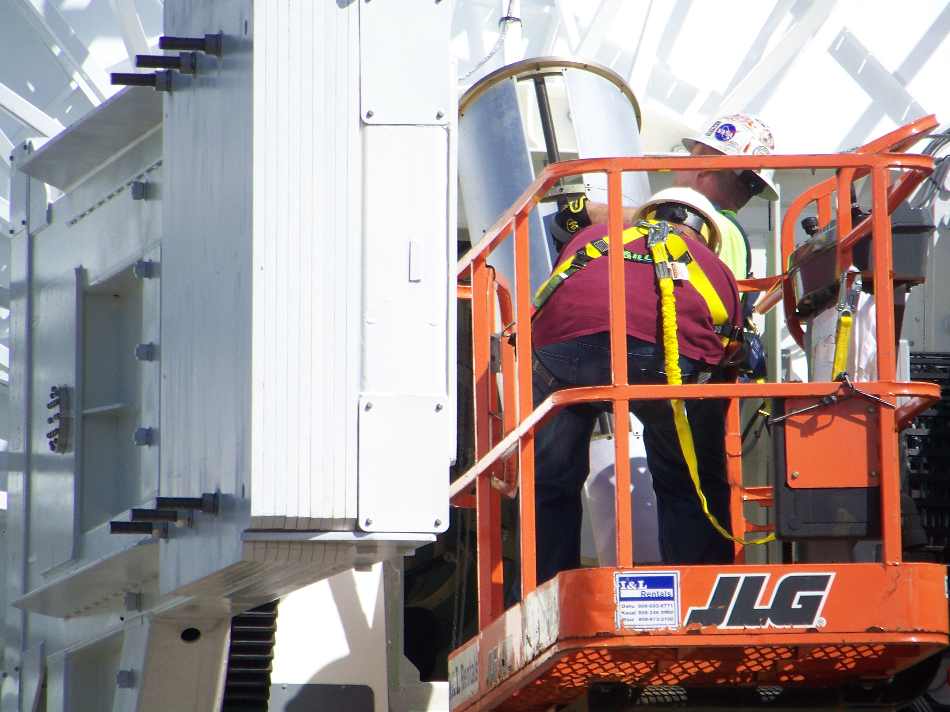
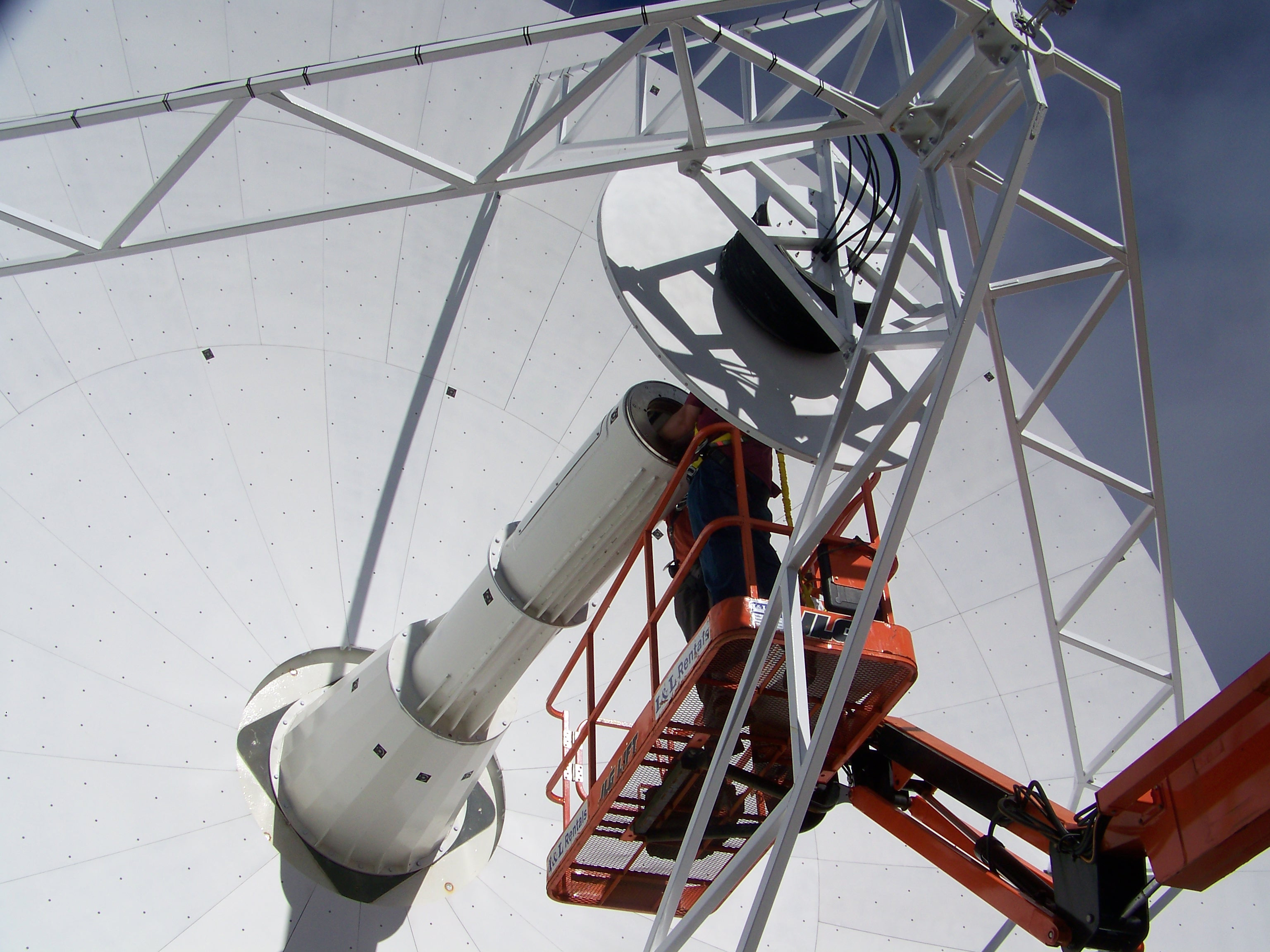
Two lifting vehicles were used in order to install the Helium compressor. The man-lift brought team members up to the hub above the mounting platform, then the forklift lifted the compressor with tag lines well away from the suspended load, finally the manlift was used again to help the team fasten the compressor to the platform after it was lifted in place.
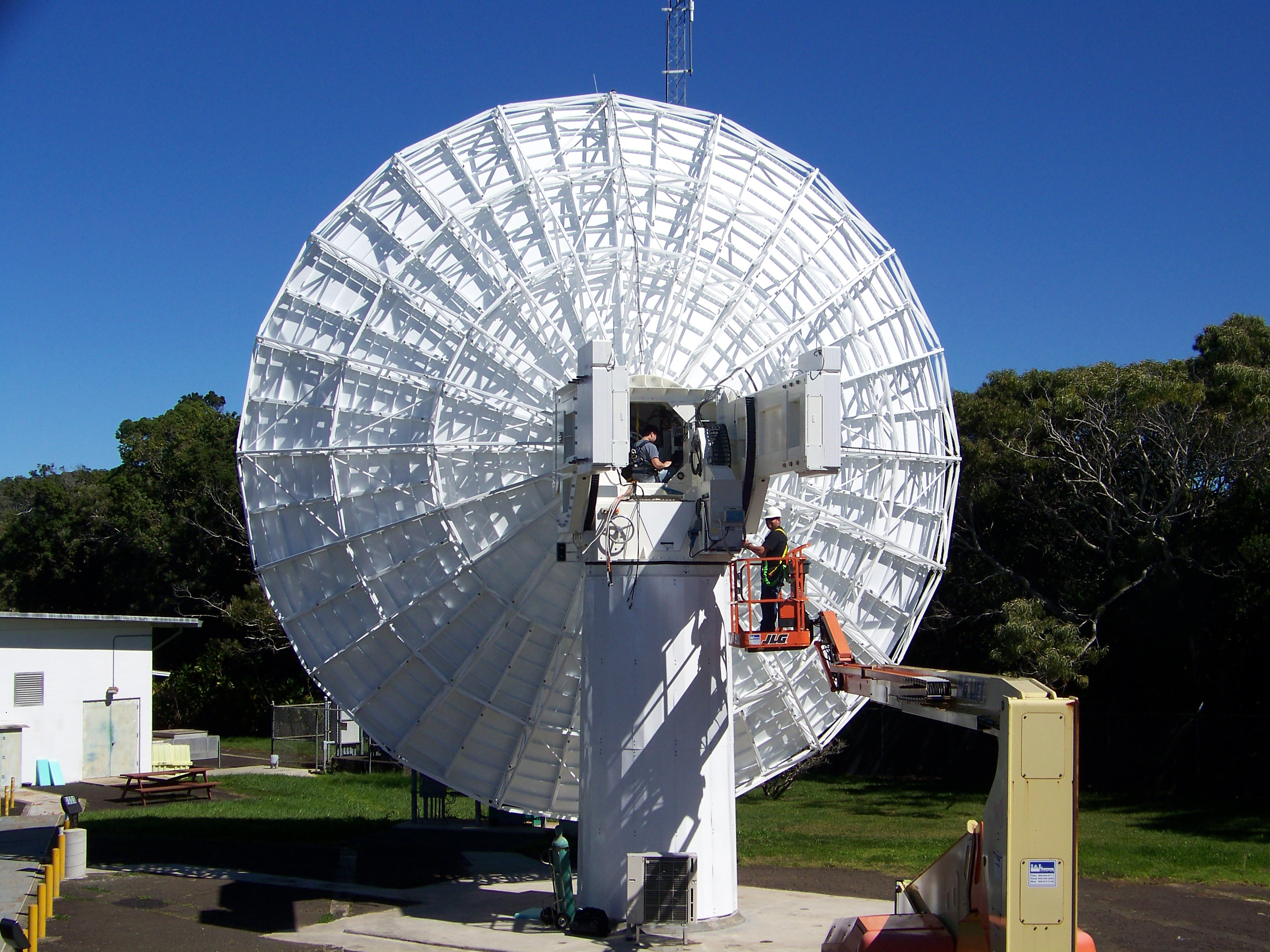
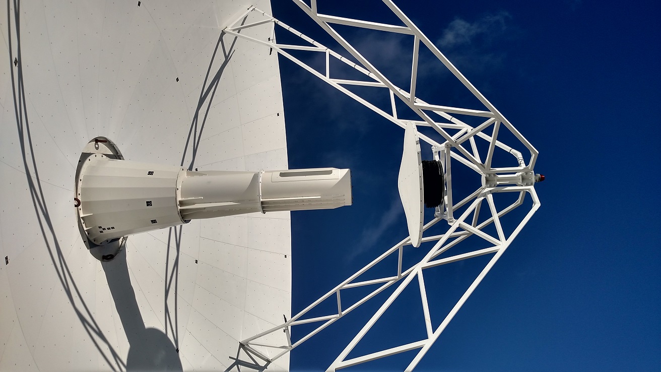
The full view of the antenna from behind the reflector shows the access to the hub electronics box and a closeup view shows the working light inside the hub electronics box (HEB). This short movie shows the frontend payload minus the post dewar electronics headed up to the focused position for a mechanical test that can be controlled from the HEB or from inside the KPGO operations room.
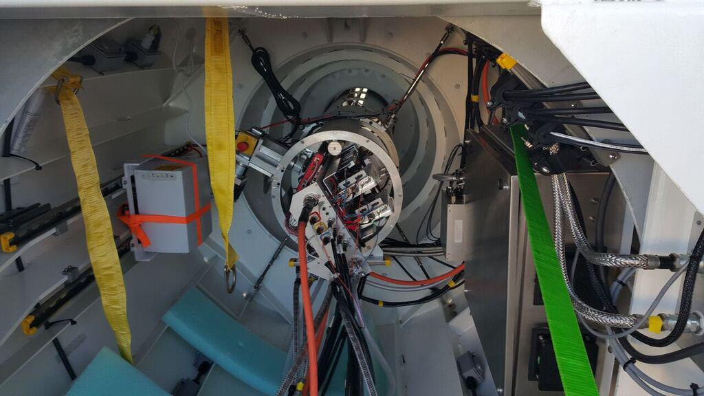
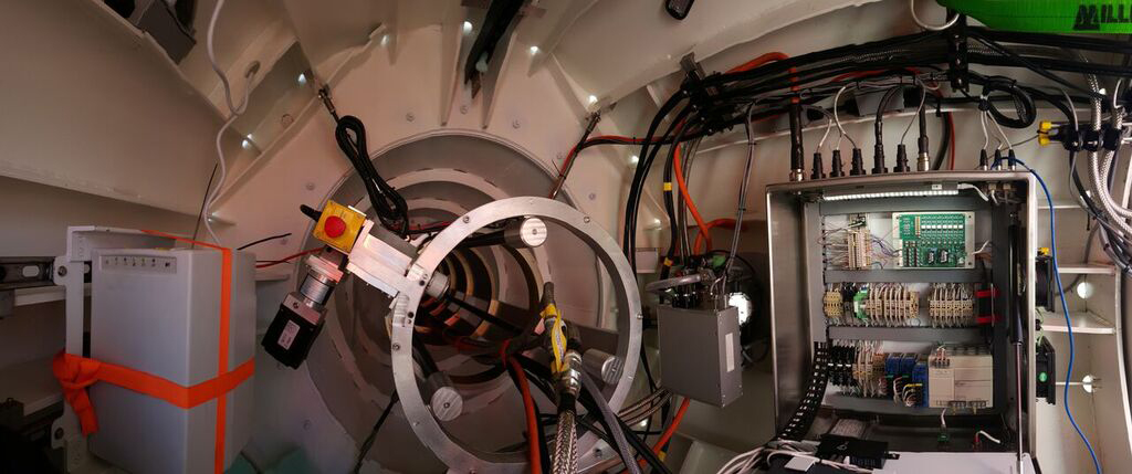
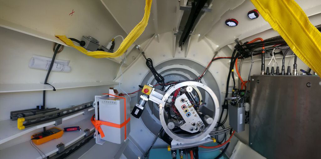
This 180 degree panoramic shot of the frontend equipment inside the hub was taken after full cabling and He lines attached. The post dewar electronics sled is now attached. In the photo on the right the frontend payload has moved down the feed cone to the focused position and the hub electronics box is open for access to the MCI hub computer.
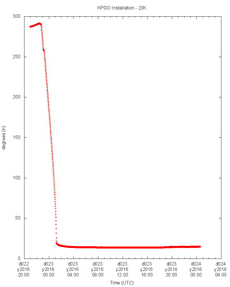
The access plate provided a way to install the locking collar before the payload was moved to a zenith pointing position. In that configuration, a dynamic inspection of the elevation cable tray was made from the manlift up to the zenith position and back down to a horizontal position. Finally, the cooling system was supplied with Helium, and the antenna was stowed. The 20K cooling requirement was met in 3-4 hours, and the temperature held stably throughout the weekend.
Arrival, Installation and Integration of the Signal Chain Backend Components at KPGO
January 21, 2016
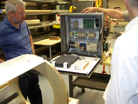
All the Signal Chain equipment arrived safely at KPGO! The Signal Chain integration team travelled to Hawaii and began equipment checkout on January 8. They verified that nothing got damaged during shipping and proceeded with the backend installation, integration, and verification. Shown below are the configuration and pictures of the assembled backend.
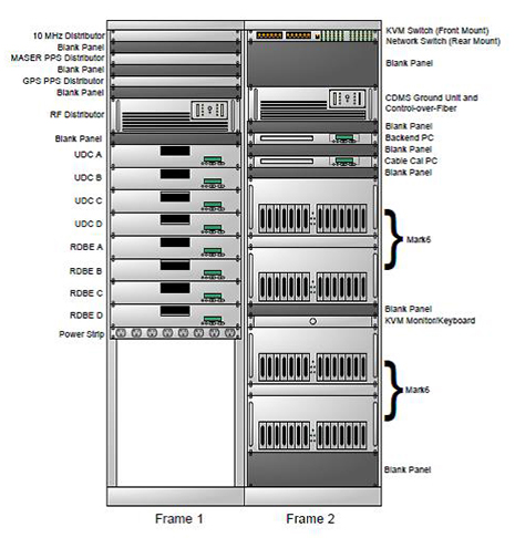
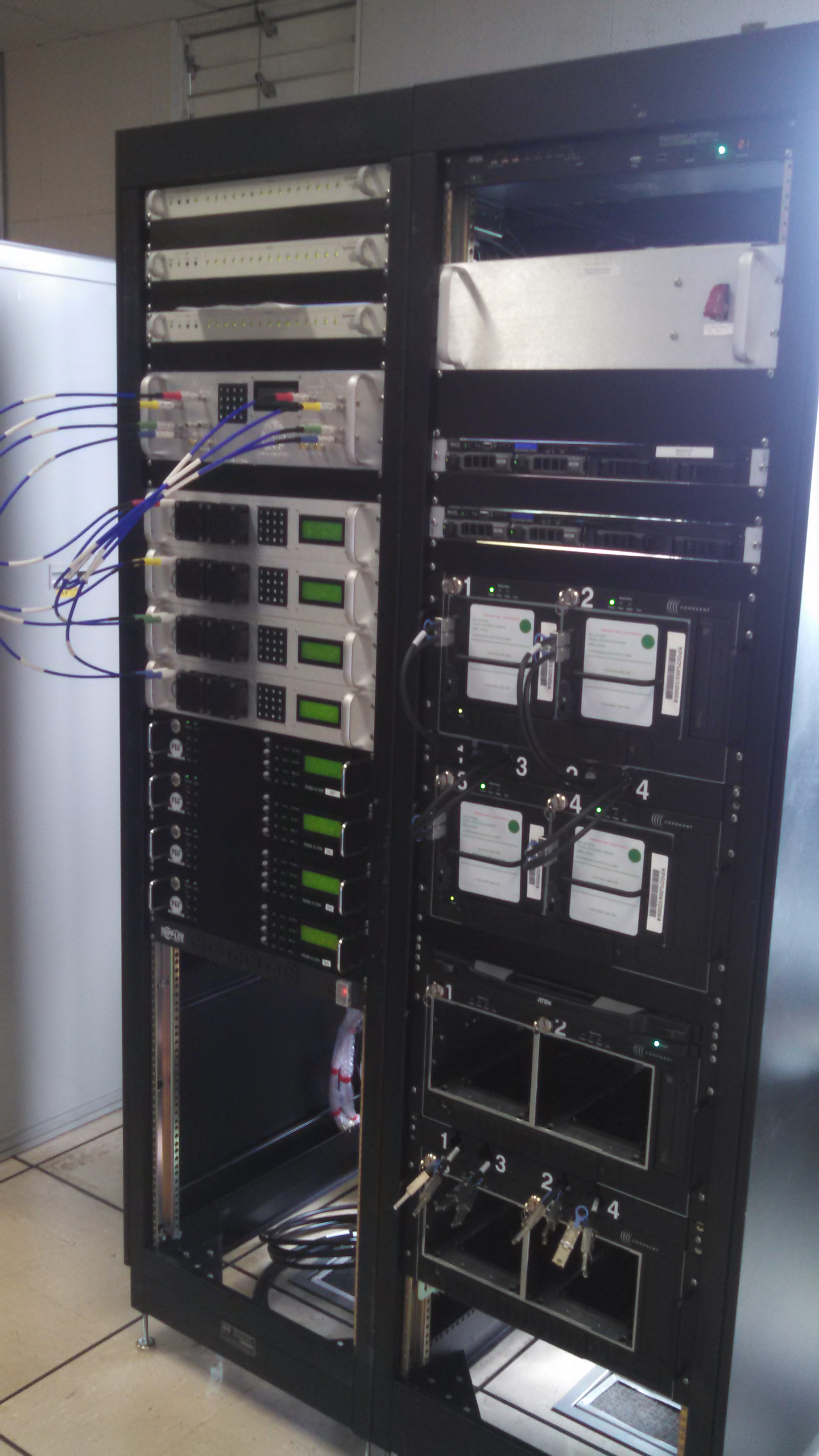
The left rack of the backend contains: 4 up-down converters (UDC) that down-convert the desired sky frequencies, 4 ROACH Digital Backend (RDBE) boxes, the RF Distribution box, the 10 MHz frequency distributor, and 2 time distribution amplifiers that provide references around the system. The right rack contains: the Mark6 recorders, the cable delay measurement system (CDMS) computer, the backend computer, and the switch on the top rails that allows sharing of the keyboard, video display, and mouse and network switches installed in the back of the rack.
Time lapsed video of the integration process.
This January 15th photo shows an installed CDMS ground Unit, which arrived after the above video was made. The unit arrived later because it was completing antenna and ground unit testing at Westford alongside the Legacy Cable Calibration system when the rest of the equipment was shipped.
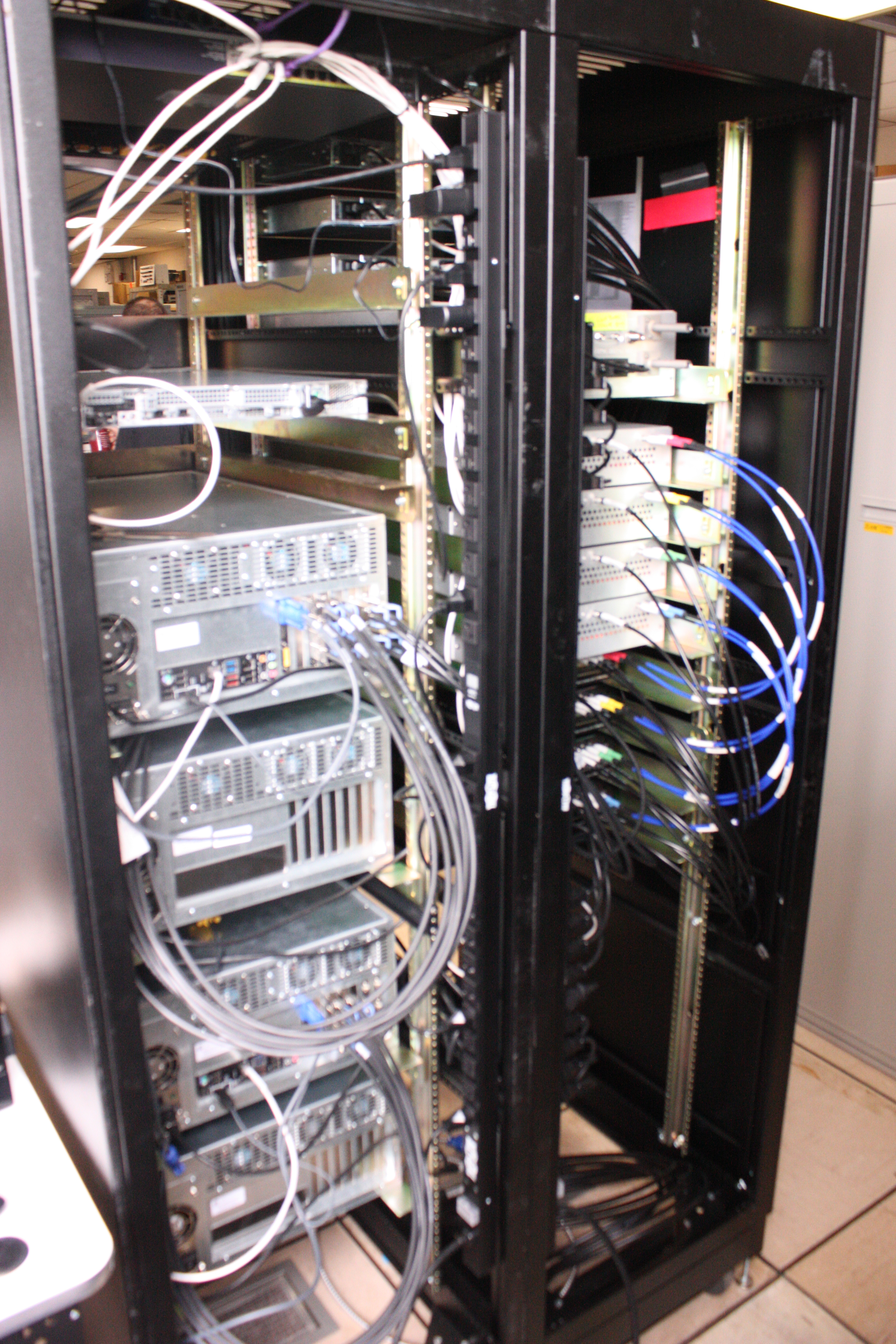
This photo shows the cabling and labeling behind the backend rack now that it is fully integrated for subsystem tests.
KPGO Signal Chain System Integration/Pre-Shipment Reviews
January 05, 2016
The signal chain development team at MIT Haystack Observatory hosted and passed system integration and pre-shipment reviews in Westford, Massachusetts, on December 15th and 16th. Integration and testing of all signal chain subsystems were reviewed including the recently completed system noise temperature tests on the frontend components, the zero-baseline tests between the KPGO backend temporarily located at the Westford site and the complete Westford system, and the plans for continuing testing the cable delay measurement system at Westford after the frontend and backend are shipped to KPGO.
Reviewing also included the horizontal installation of the frontend positioner (FEP) hardware into the 12-meter antenna feed cone. This procedure was re-engineered (described in the December 10 post) because of differences in the antenna hub from the prototype 12-meter antenna and FEP at GGAO. The end result, which is a much safer procedure, uses a trolley that minimizes the confined space and fall hazards with the VGOS stations, and makes the hub a more comfortable working environment.
The removable support hardware sled with post-dewar electronics is in the foreground of this photo taken of the complete frontend payload. Cryogenic coolant cables and components are accessed from the other side.
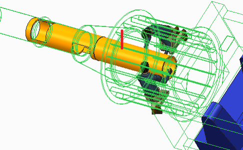
The two movies illustrate and demonstrate (in CAD design animation) the access to the hub electronics box in the hub of the antenna. Chris Eckert, lead mechanical engineer of the signal chain, explains the movements of components in the hub.

Backend configuration at the Westford station. The two black racks are the completed KPGO backend and blue racks in the background are the operating broadband backend for the Westford antenna.

The KPGO backend computer with the split of the incoming RF signal occurring after the Westford RF-distributor. Chester Ruszczyk, KPGO Signal Chain Project Manager and Systems Engineer, demonstrates the interrogation of the system configuration from the backend computer.
KPGO Signal Chain Accessibility
December 10, 2015
Early in the development process of the KPGO station, the team identified several accessibility and safety issues associated with the planned installation of the front end positioner. The primary issue related to the confined space in the hub and lessons learned from the vertical installation of the GGAO front end positioner. The team came up with a great solution for installing the positioner in a horizontal position that is much safer for the personnel than the originally planed vertical installation.
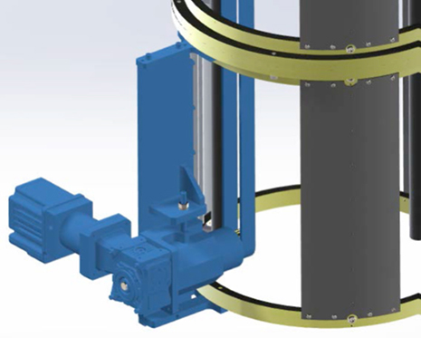
The payload drive system (in blue) can be serviced in the hub maintenance position
The primary service panel allows access to payload interface and the secondary vacuum port and the LNA bias supplies, electronics tray and calibrator that are accessible and removable
In the secondary service panel the turbo pump, vacuum valve, vacuum gauge and the DAQ cards are removable, the calibrator and payload interface are accessible
Goddard review team members get an explanation of the serviceability of the hub electronics box at Haystack Observatory in July 2015.
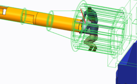
Model based description of installing the signal chain rails inside the hub for the frontend payload positioning system
KPGO Signal Chain Frontend Integration and Outdoor Testing
November 23, 2015
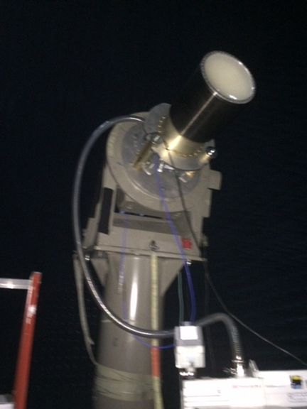
The signal chain frontend is a delicate piece of radio-frequency engineering. Heretofore, components development, characterization, and testing have been done in controlled indoor environments such as the shield room at the MIT Haystack Observatory and the anechoic chamber at MIT Lincoln Laboratory. Recently, the completed KPGO frontend was taken outdoors for comprehensive radio testing under realistic open-sky conditions. The frontend tests exercised all subsystem components but the horizontal positioner, which largely provides mechanical coupling to the antenna. The tests confirmed high-quality measurements in the high-frequency band. Despite the radio-quiet time enforced during the tests at Haystack, radio signals from mobiles and other wireless devices are ubiquitous in the low-frequency band. Suitably, signal interference is known to be less of an issue at the KPGO site.
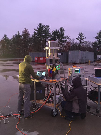
The completed KPGO frontend, minus the positioner, looking straight up towards the sky during early morning testing on the grounds of the MIT Haystack Observatory. The test involved the entire frontend signal path, from the feed, through the cooled receiver and high-low bands, along the antenna cables, to the radio-frequency distributor. At KPGO, the latter is already part of the backend rack.
KPGO Signal Chain Backend Development
November 02, 2015
The signal chain development team at MIT Haystack Observatory has passed a key milestone in completing the full backend integration in their electronics laboratory. The backend subsystem involved the RF distributor, up-down converters, digitizers, and recorders. The completed backend subsystem has now been transported to and integrated at the Westford station, where a comprehensive series of KPGO-like observing and validation tests will be conducted, including zero-baseline tests side-by-side with the existing Westford broadband geodetic system.
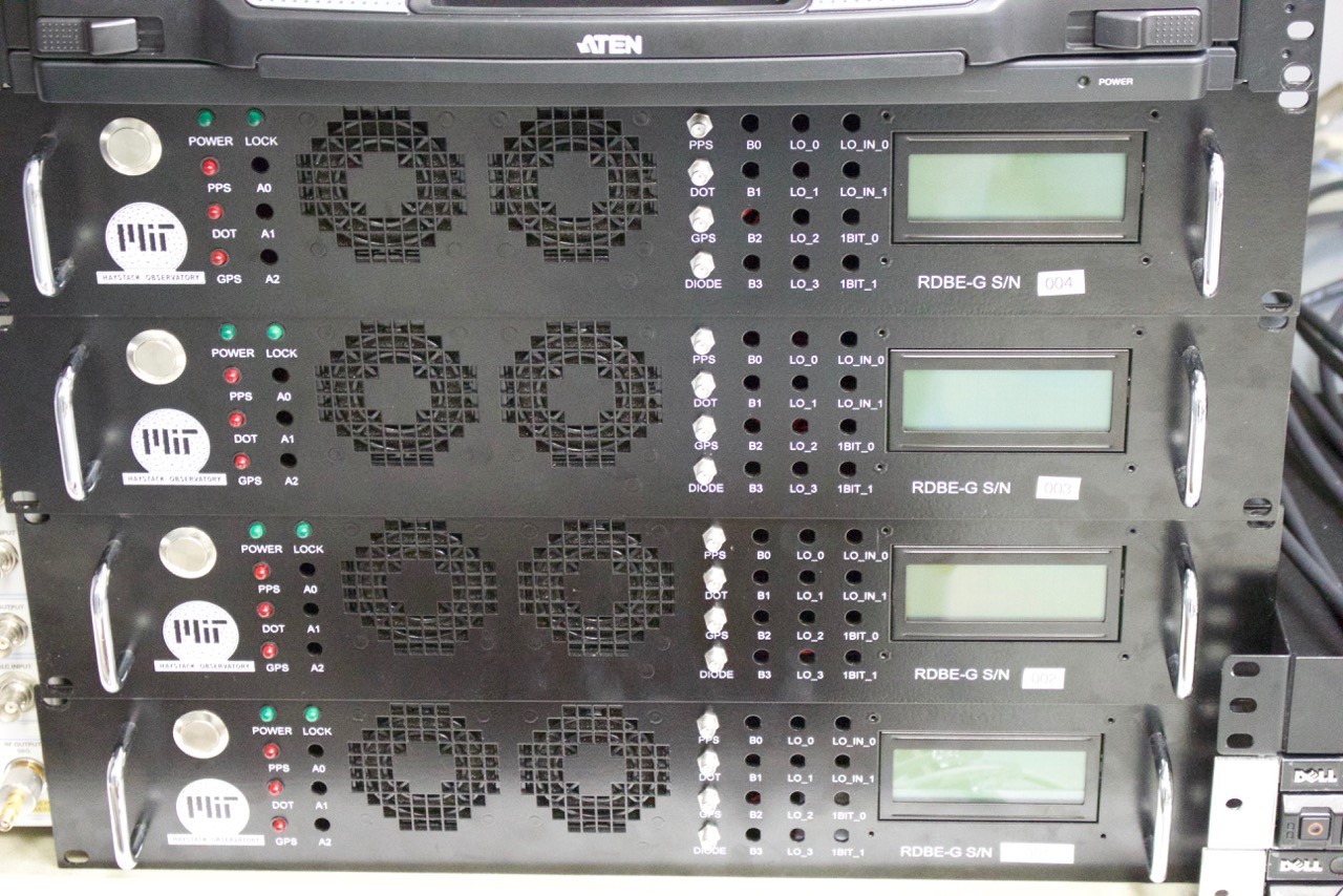
Detail of the four digitizers (a.k.a. RBDE-G), which sample and quantize the down-converted broadband analog signals into 8 digital streams (2 polarizations each) recorded by the Mark 6 recorder.
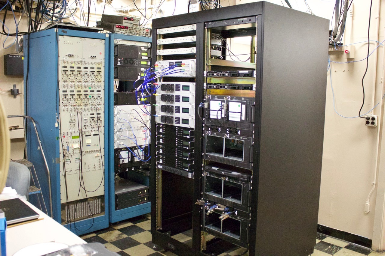
The completed (black rack) KPGO backend standing next to the (blue rack) Westford broadband backend. Shown from top to bottom are (left) the frequency and time reference distribution amplifiers, radio-frequency distributor, up-down converters, digitizers, server, and (right) two Mark6 recorders.
KPGO Antenna System Acceptance Tests
October 12, 2015
The KPGO Antenna passed all the System Acceptance Tests on October 11, 2015! Congratulations to the Intertronics Systems, Inc. team and the KPGO staff for completing the installation! The keys to the antenna were handed over to the KPGO staff and the antenna is now under Field System control.

Intertronics Solutions, Inc. performs one of the system acceptance tests by successfully pointing at the Sun. The shadows indicate that this was a successful test.
Peter and Stephen Shield from Intertronics Solutions, Inc. demonstrate the antenna control to Brian Luzum from USNO and Darryl Lakins from NASA/GSFC.
Videos from Antenna and Signal Chain development
October 08, 2015
Back in June 2015, the KPGO Antenna development team conducted a series of tests at their factory in Quebec. After those tests, a video of the operating antenna was made by the KPGO Signal Chain development team who were visiting to plan the installation of the front end positioner in the hub. A video of the front end traveling from the maintenance position to the observation position in the feed cone will bring the KPGO antenna to life in 2016 when these subsystems are integrated and tested.
Video of Haystack Observatory operation of the front end positioner from the payload in its maintenance position in the hub to its observation position in the lab.
Video of Intertronics Solutions, Inc. operation of the 12 meter antenna after the Factory Acceptance Test in Quebec in June 2015.
Sub reflector and Feedcone Photogrammetry and Preparation for the Antenna System Acceptance Tests
October 08, 2015
This week at KPGO the final preparations were underway for the Antenna System Acceptance Test (SAT) which repeat many of the factory acceptance tests done in Quebec. One capability that will be available for the SAT that is new since the FAT, is the use of the hexapod to make fine adjustments to the subreflector position. The installation and operation of the hexapod will further automate the fine adjustment procedure to be done with the signal chain in January. Photogrammetry was repeated this week with the hexapod fine tuning the subreflector position at several elevation angles and measurements of the feed cone position sag. The SAT will be conducted with a single hexapod adjustment that works best over all elevation angles from horizon to zenith.

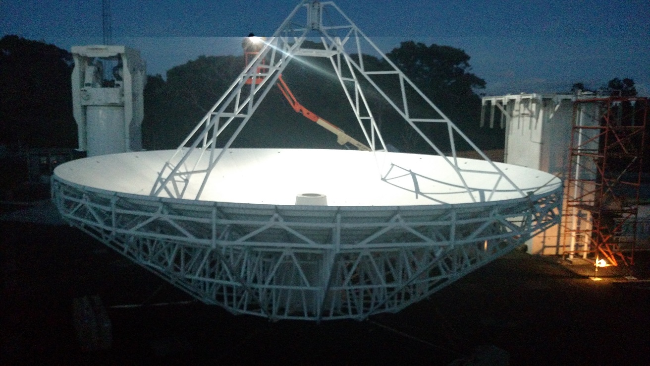
An after-dark closeup of the main reflector shows the targets used for photogrammetry.
Antenna team verifying hexapod movement directions.
Photogrammetry at zenith after subreflector adjustments using hexapod.
Photogrammetry at the horizon after subreflector adjustments using hexapod.
Feed cone access panels being installed for signal chain front end positioner to come in January 2016.

Feed cone targets removed after completion of photogrammetry sessions at various elevations from horizon to zenith.
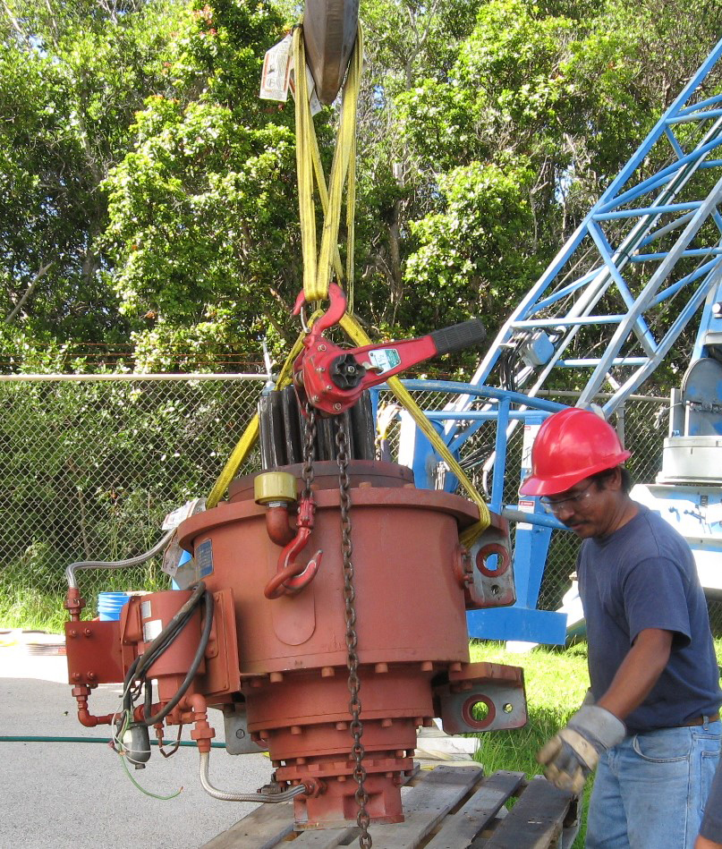
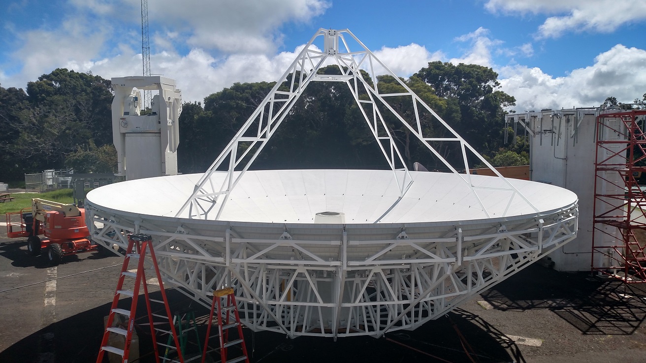
Reflector Lift
October 02, 2015
For the last two weeks the Kokee Park Geophysical Observatory (KPGO) has been a two-shift operation where the ISI 12m antenna installation team has been working with the Harris operations team to shoot distributed reflectors from various angles in the near field of the main reflector. The reflector surface accuracy error RMS was .005" after the ninth iteration of photogrammetry shots. On October 1st, the 12 meter reflector was lifted by crane to its position on the antenna pedestal and retained the RMS surface accuracy achieved in the tests taken and adjustments made on the ground. Photogrammetry continues and the surface accuracy will be measured from various elevation angles.
At Haystack Observatory, final plans are being practiced for the installation as well as maintenance procedures of the front end positioner inside the feed cone of the antenna. The analysis of quad ridge flared horn (QRFH) feedhorn antenna patterns taken at MIT - Lincoln Laboratory are also nearly ready for release.
First Photogrammetry session on the assembled reflector (9/18/2015)

Installing the crane rigging for the reflector (10/1/2015)
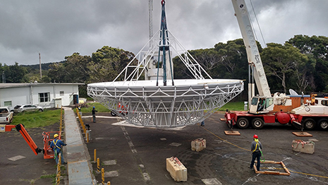
Controlled lift of the reflector begins
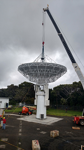
Reflector placed on the turning head and elevation arms
The feed cone is lifted into place with the crane and attached with the manlift providing access
The subreflector is attached to the hexapod interface across from the feed cone
Photogrammetry resumes with antenna in the zenith position. The reflector surface accuracy error RMS was verified still to be .005 inches (10/1/2015).
Signal Chain Front-end Integration at MIT Haystack Observatory
October 02, 2015
The VGOS signal chain front end includes a number of mechanical and electrical elements such as the antenna feed, receiver payload, receiver cryogenics and vacuum, and calibration and monitoring systems, all housed inside a mechanical positioner that fits inside the KPGO feed cone. Fabrication of the signal chain front end has been completed, and the system is currently going through integration and testing in preparation for shipping to Hawaii.
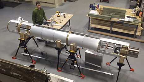
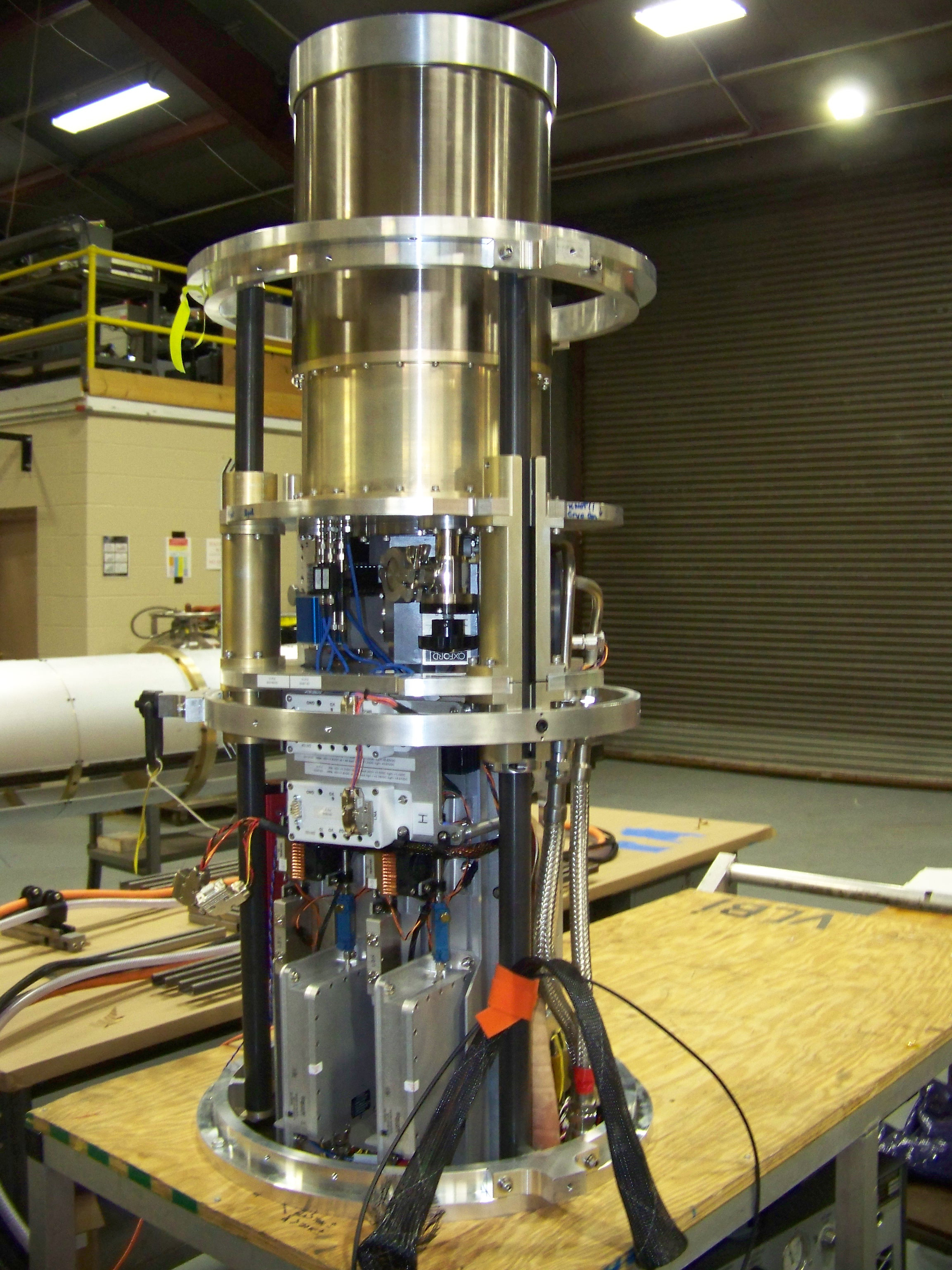
Front-end positioner during electromechanical tests conducted at the MIT Haystack Observatory facilities. The receiver payload (cylinder and electronic trays on the right end of the positioner) can travel along the positioner for service and safety, and is shown here in "observation" location.
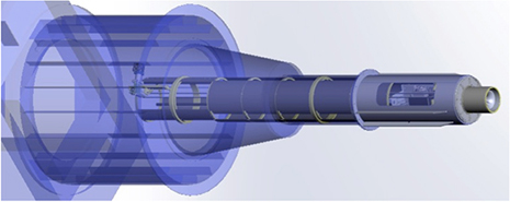
When mounted on the KPGO antenna, the front-end positioner will fit inside the antenna feed cone.
The front-end subsystem test team used the Anechoic Test Range at the MIT Lincoln Laboratory to characterize the antenna feed patterns.
Signal Chain Introduction
September 25, 2015
MIT Haystack Observatory has been at the forefront of VLBI technology development since the birth of the technique many decades ago. The broadband signal chain of the new KPGO radio telescope is a major contribution that results from this development. The KPGO signal chain builds on the successful designs already implemented at the GGAO 12-m and the Westford 18-m telescopes. This two-element prototype of a VGOS baseline is the only fully functional broadband VGOS system completed to date.
The signal chain encompasses a series of novel VGOS components along which the incoming radio signal propagates once it enters the telescope, from the delicate cryogenically-cooled feed and receiver up in the antenna front end, through sensitive coaxial and fiber optic cables that connect the front and back ends, to advanced sampling and recording subsystems down in the back end. If the fully-steerable VGOS antenna structure can be viewed as a mechanical "listening ear," the signal chain is its electronics "beating heart."
The VGOS signal is broadband because it spans a bandwidth of over 10 GHz, with microwave frequencies ranging between approximately 2 GHz (15-cm wavelength) and 14 GHz (2-cm wavelength). The signal, which is analog in the front end, is transmitted via cables to the back end, where carefully selected sections of the entire broadband are digitized. To meet the stringent accuracy requirements of VGOS, the signal chain also incorporates a highly sophisticated calibration system that tracks the various delays introduced by each component along the entire broadband signal path. Interferometry is ultimately realized when the signals recorded at KPGO and other broadband VGOS-compliant systems, independently but simultaneously, are brought together for complex correlation and post-processing, and geodetic analysis and beyond.
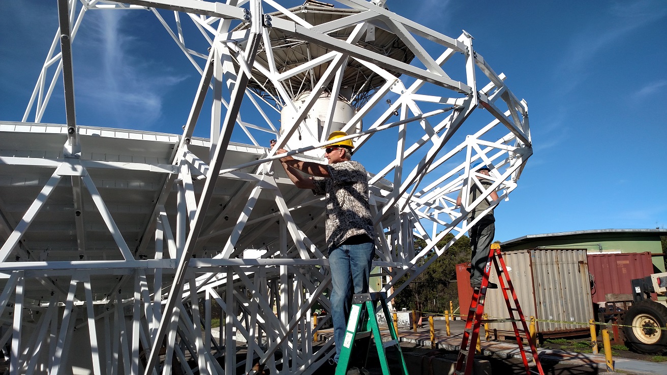
Antenna Team Attaches Reflector Panels
September 18, 2015
Throughout the week at Kokee Park, the antenna team turned their attention to re-installing reflector panels that were carefully handled after the factory acceptance test (FAT) in Montreal. All of the adjustments were recorded after the photogrammetry measurements so that the re-test in Hawaii will be faster than the initial adjustments.
First Inner panel installed on reflector dish
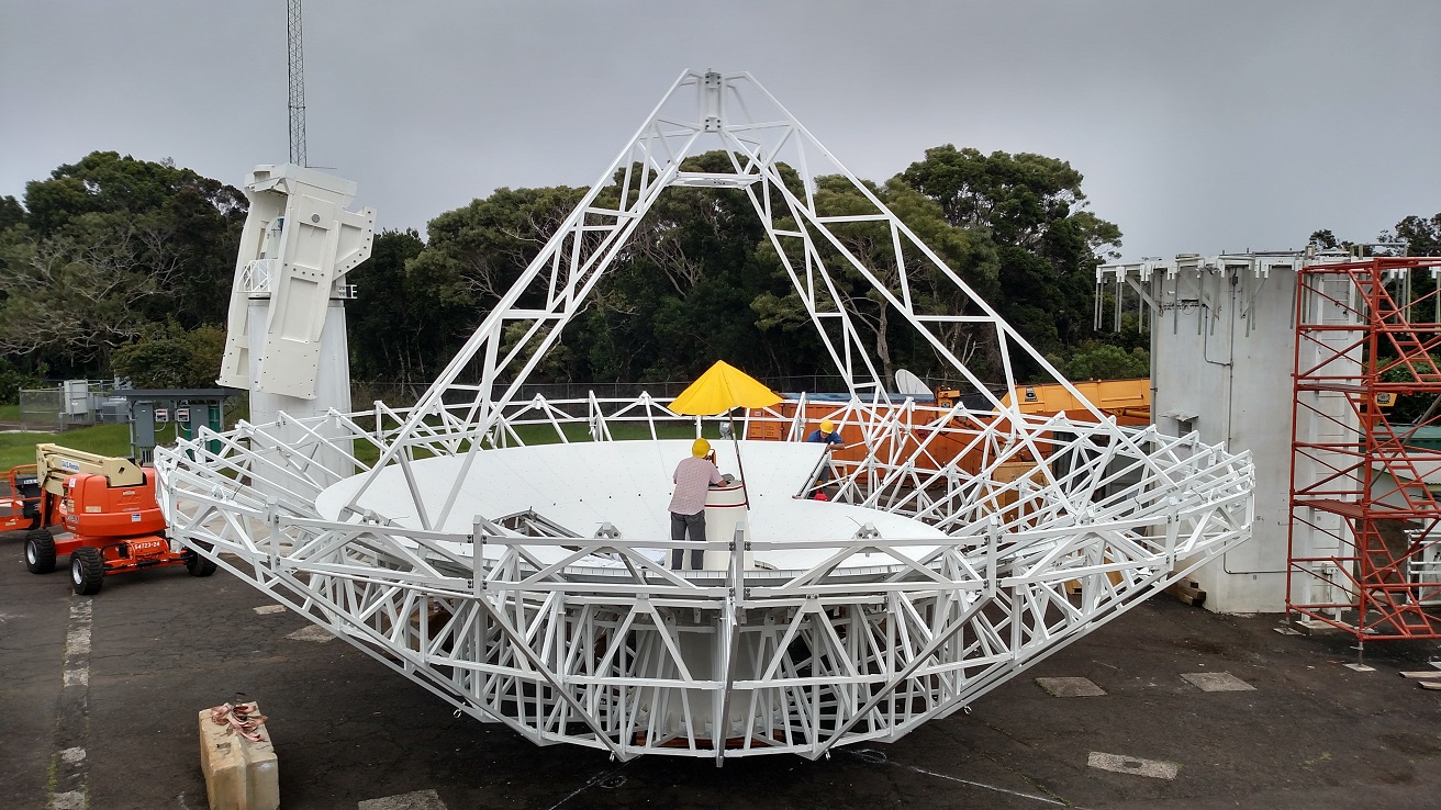
Mid-panel installation in progress
Installing mounting hardware for the outer panels
Outer panel installation complete
Antenna Team begins reflector assembly
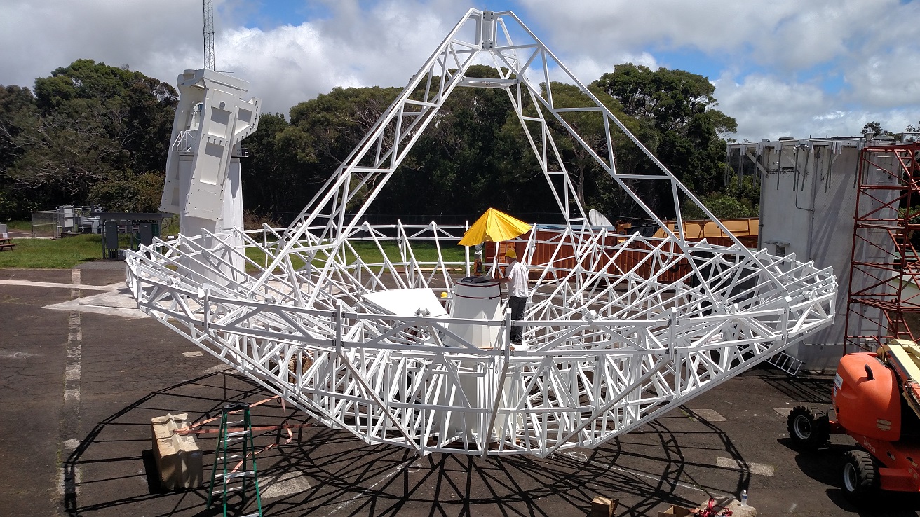
September 11, 2015
Intertronics Solutions, Inc. (ISI) worked together with the KPGO operations team on the installation of the 12-meter antenna. The elevation counterweights were attached, and the encoder and limit switches were tested. A lot of progress was made in assembling the reflector dish. The data lines were also connected to the antenna and the operations table.
Installation of the counterweights.
The antenna movement was tested after the elevation encoder and limit switch installation.
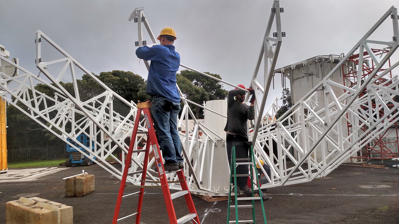
Installing the main rib diagonal supports of the antenna reflector dish.
View from the 20 meter KPGO antenna.
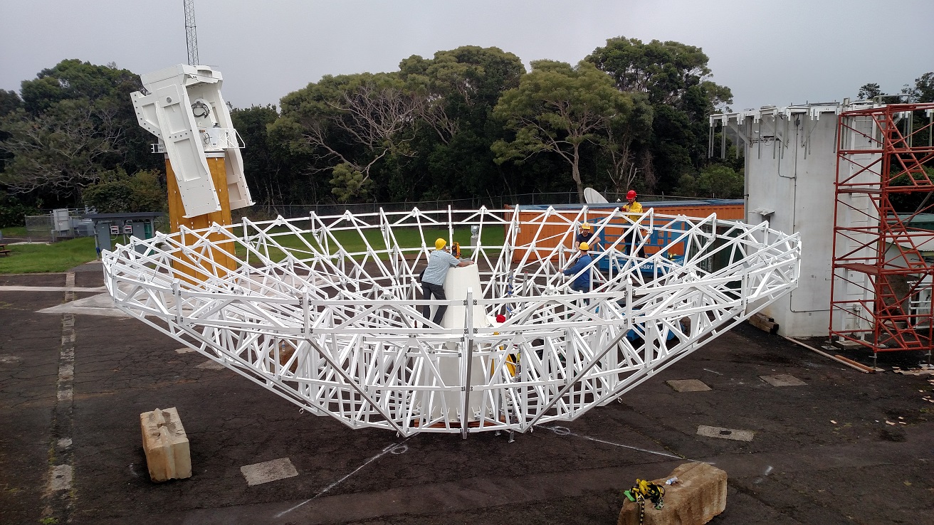
Positioning the reflector dish ribs using a theodolite.
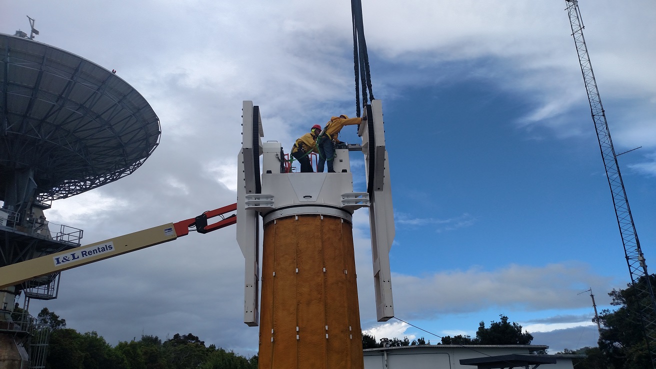
Start of Antenna Installation
September 04, 2015
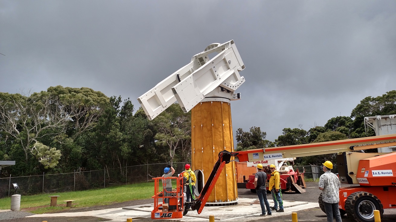
The installation of the 12-meter Intertronics Solutions, Inc. (ISI) antenna at KPGO began on September 1, 2015. The antenna passed its Factory Acceptance Test in June 2015 and was disassembled and shipped from ISI’s facility in Canada to Hawaii. Shown below is the removal of the antenna pedestal from its shipping container and its vertical installation on the concrete pad. ISI will continue to assemble the antenna over the next few weeks and perform a Site Acceptance Test of the antenna in October.
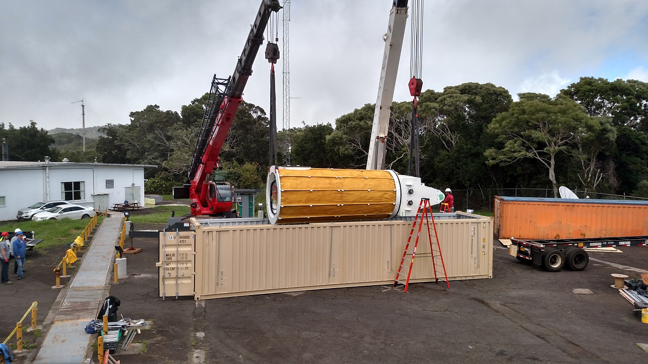
Antenna pedestal after removal from its shipping container.
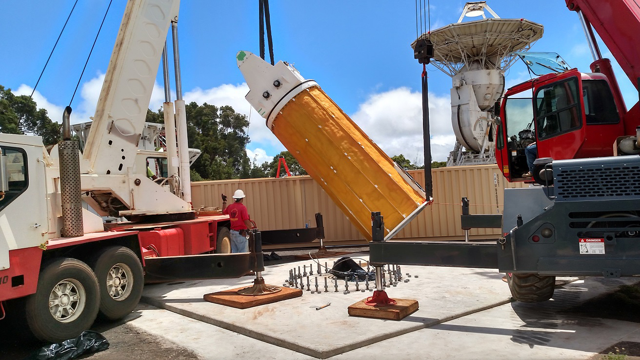
Lifting the pedestal

Positioning the pedestal
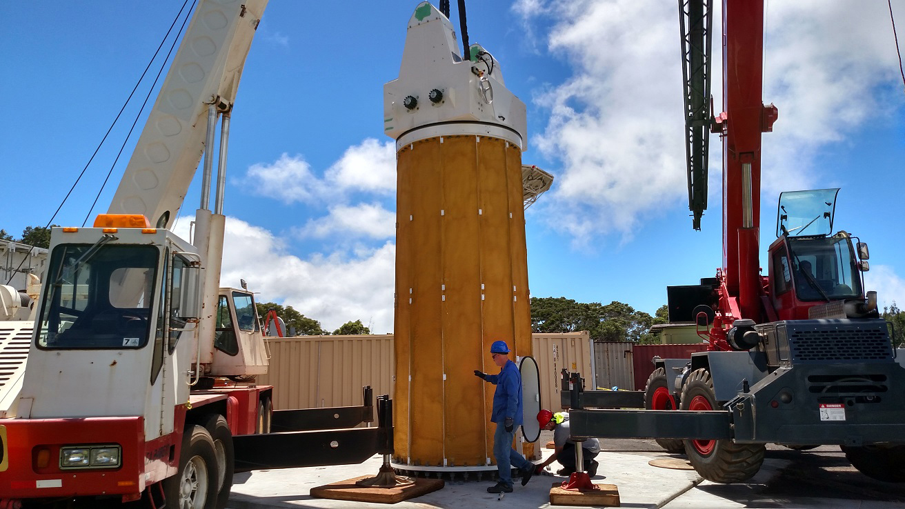
Pedestal installed on the concrete pad