VLBI at GGAO
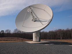
The GGAO VLBI radio telescope is used as: (1) a fiducial location in the global terrestrial reference frame, (2) as one of two unique test sites for the next generation VLBI system, and (3) as one of several sites participating in a series of VLBI observing sessions to gather data used to model tropospheric refraction. The mobile VLBI system MV-3 was permanently located at GGAO starting in 1989 and was eventually transformed into the fixed antenna configuration in the 1992-1993 timeframe.
- VGOS - To improve VLBI data to meet increasingly demanding requirements, an end-to-end redesign called the VLBI Global Observing System (VGOS, formerly VLBI2010) is in progress.
To improve VLBI data to meet increasingly demanding requirements, an end-to-end redesign called the VLBI Global Observing System (VGOS, formerly VLBI2010) is in progress. The key concepts are a broadband signal acquisition chain (2-14 GHz) with digital electronics and fast, small antennas. By placing up to four carefully chosen RF bands in the 2–14 GHz range, Radio Frequency Interference (RFI) should be ameliorated and the requisite observation precision achieved. Fast antennas will provide many more observations. More observations support higher temporal and spatial resolution in estimating the effect of the troposphere at each station. Simulations show tropospheric effects as the largest noise source. High recording bandwidths are required to achieve the necessary sensitivity.
VGOS has been developed to be minimally staffed, remotely controllable, broadband, RFI avoiding, fully digital, fast slewing, and capable of producing VLBI delays with precision of 4 picoseconds (in 4 picoseconds light travels 1 millimeter.) The system is designed to observe continuously. The broadband design has been implemented on two prototype systems, the 12-m antenna at GGAO and at the 18-m antenna at Westford, MA. These two antennas began geodetic VLBI observations in December 2014.
The GGAO 12-m VGOS antenna includes the following features:
- four bands of 512 MHz each, rather than the two (S and X) for the legacy Mark IV systems,
- dual-linear polarization in all bands,
- multi-tone phase/cal delay for every channel in both polarizations,
- group delay estimation from the full spanned bandwidth (3.0 GHz to 10.5 GHz),
- simultaneous estimation of the group delay and the total electron content difference (dTEC) between sites using the phases across all four bands.
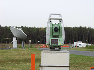
- VTS - The Vector Tie System (VTS) is a combination of a precise local-tie survey and a periodic monitoring system using one or more Robotic Total Stations (RTS) and other instrumentation for measuring the site stability (tilt meters, etc.).
The Vector Tie System (VTS) is a combination of a precise local-tie survey and a periodic monitoring system using one or more Robotic Total Stations (RTS) and other instrumentation for measuring the site stability (tilt meters, etc.). The GGAO implementation demonstrated the ability to monitor the site semi-autonomously with sub-millimeter accuracy. This included the ability to find and identify the target prisms, verify the prism correction, and compensate for atmospheric conditions.
- The Legacy VLBI system is a 5-meter telescope. The mobile VLBI system MV-3 was permanently located at GGAO starting in 1989 and was eventually transformed into the final fixed antenna configuration in the winter of 2002. This system was used for operational observing and research and development. The system ceased operations in May 2007 as SGP focused resources on the development of the next generation VLBI, VGOS, at GGAO. The 5-meter telescope continued to be used after that for limited R&D purposes, such as antenna deformation research. In recent years, the 5-meter telescope has been undergoing upgrades, and it is currently not operable.
- NEOS-A sessions used to determine Earth orientation and to link the celestial and terrestrial reference frames,
- T2 sessions used for terrestrial reference frame monitoring, and
- RDV sessions used for three purposes: source structure imaging and correction by USNO, determination of a high accuracy terrestrial reference frame by NASA, and provision of high quality source positions by NRAO.
- A 1-m satellite receiving dish is on site. It was used as part of an MIT Haystack Observatory project, the development of holographic imaging that Haystack planned to use to understand antenna deformation that could impact VGOS accuracy. The imaging successfully reconstructed deformations on the 5 m telescope in 2010. The 1-m dish is currently not operable.
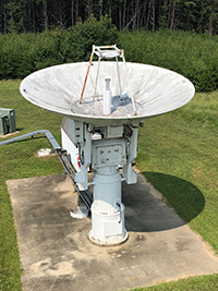
The GGAO VLBI 5-m antenna in 2018.
The GGAO 5-m antenna was constructed in 1982 and was operated as a mobile unit, MV-3, until it was brought to GGAO and installed on first a semi-permanent basis and then a permanent basis by 2002. It had a Cassegrain feed and observed in X-band (8.18 to 8.98 GHz) and S-band (2.21 to 2.45 GHz). It had a 540 degree azimuth range and a 90 degree elevation range, and it could slew at 3 degrees per second in azimuth and in elevation.
The GGAO 5-m antenna participated in many VLBI experiments through May 2007. These included primarily the following IVS sessions:
But the 5-m antenna also supported miscellaneous sessions as needed.
Currently GGAO is focusing its attention on VGOS observing, and the 5-m antenna has been deactivated for legacy (S/X) observing and partially configured for future VGOS use.
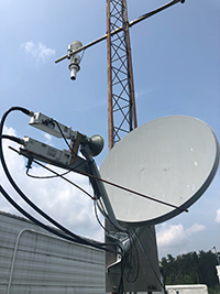
GGAO 1 m antenna
Deviations from the smoothness of an antenna's surface (deformations) affect the movement of the antenna. These deformations must be identified and taken into account using modeling. The GGAO VLBI 1-m antenna was used successfully in 2010 in an experiment which tried to detect deformations of another VLBI antenna by using holographic imaging. The photos below show the results.
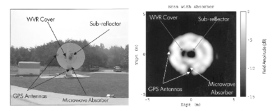 The VLBI 5-m antenna was used as the test subject. The left photo shows the 5-m antenna with five objects that were normally part of the antenna dish, or attached to the antenna dish for testing, and deformed an area of the antenna. These objects were, clockwise from the bottom right, a microwave absorber, two GPS antennas, a Water Vapor Radiometer cover, and the antenna's sub-reflector. In a successful holographic image, a smooth antenna dish should appear as a light background and any deformations should appear as darker patches. As shown in the right figure, all five of the objects were clearly detected as dark areas. This test demonstrated the viability of using the 1-m antenna to detect deformations on other VLBI antennas.


